CCNA Todd Lammle Ch 10 - 16
Textbook Notes by Michael Banks 2021-2023
(The jumping around between colors: a memory-hack i was trying for the exam!)
Chapter 10, Layer 2 Switching and STP - Exercises
Switch 1 setup - 2960, 24-port (book version of this model is 8-port)
SW1(config)#
enable secret todd
SW1(config)#
int f0/1
SW1(config-if)#
description 1st connection to core switch
SW1(config-if)#
int f0/2
SW1(config-if)#
desc 2nd connection to core switch
SW1(config-if)#
int f0/3
SW1(config-if)#
desc connection to HostA
SW1(config-if)#
int f0/4
SW1(config-if)#
desc connection to PhoneA
SW1(config-if)#
int f0/8
SW1(config-if)#
desc connection to IVR
SW1(config-if)#
line console 0
SW1(config-line)#
password console
SW1(config-line)#
login
SW1(config-line)#
exit
SW1(config)#
line vty ?
<0-15> First Line number
SW1(config)#
line vty 0 15
SW1(config-line)#
password telnet
SW1(config-line)#
login
SW1(config-line)#
int vlan 1
SW1(config-if)#
ip addr 192.168.10.17 255.255.255.240
SW1(config-if)#
no shut
%LINK-5-CHANGED: Interface Vlan1, changed state to up
SW1(config-if)#
exit
SW1(config)#
banner motd # MOTD: This is the SW1 switch #
SW1(config)#
exit
%SYS-5-CONFIG_I: Configured from console by console
SW1#
copy run start
Destination filename [startup-config]?
ENTER
Building configuration...
[OK]
Switch 2 setup - 3560, 24-port (book version of this model is 8-port)
SW2(config)#
enable secret todd
SW2(config)#
int f0/1
SW2(config-if)#
description 1st connection to core switch
SW2(config-if)#
int f0/2
SW2(config-if)#
desc 2nd connection to core switch
SW2(config-if)#
int f0/3
SW2(config-if)#
desc connection to HostB
SW2(config-if)#
int f0/4
SW2(config-if)#
desc connection to PhoneB
SW2(config-if)#
line console 0
SW2(config-line)#
password console
SW2(config-line)#
login
SW2(config-line)#
exit
SW2(config)#
line vty ?
<0-15> First Line number
SW2(config)#
line vty 0 15
SW2(config-line)#
password telnet
SW2(config-line)#
login
SW2(config-line)#
int vlan 1
SW2(config-if)#
ip addr 192.168.10.18 255.255.255.240
S1
SW2(config-if)#
no shut
%LINK-5-CHANGED: Interface Vlan1, changed state to up
SW2(config-if)#
exit
SW2(config)#
banner motd # MOTD: This is the SW2 switch #
SW2(config)#
exit
%SYS-5-CONFIG_I: Configured from console by console
SW2#
copy run start
Destination filename [startup-config]?
ENTER
Building configuration...
[OK]
Core Switch setup - 3550 Multilayer (sub for book version 3650)
Core(config)#
enable secret todd
Core(config)#
int g1/0/1
Core(config-if)#
desc 1st connection to SW2
Core(config-if)#
int g1/0/2
Core(config-if)#
desc 2nd connection to SW2
Core(config-if)#
int g1/0/3
Core(config-if)#
desc 1st connection to SW1
Core(config-if)#
int g1/0/4
Core(config-if)#
desc 2nd connection to SW1
Core(config-if)#
line con 0
Core(config-line)#
password console
Core(config-line)#
line vty 0 15
Core(config-line)#
password telnet
Core(config-line)#
login
Core(config-line)#
int vlan 1
Core(config-if)#
ip addr 192.168.10.19 255.255.255.240
Core(config-if)#
no shut
Core(config-if)#
exit
Core(config)#
banner motd # This is the core switch #
Core(config)#
exit
Core#
copy run start
Destination filename [startup-config]?
ENTER
Building configuration...
[OK]
Prompt#
command
output
TROUBLE
I got stuck while setting up these switches. I will go through my thought process in finding the solution to the problem.
(Documenting this in HTML is very time consuming, but I think it is worthwhile)
Lets stop and take a look at exactly what the book is laying out for us:
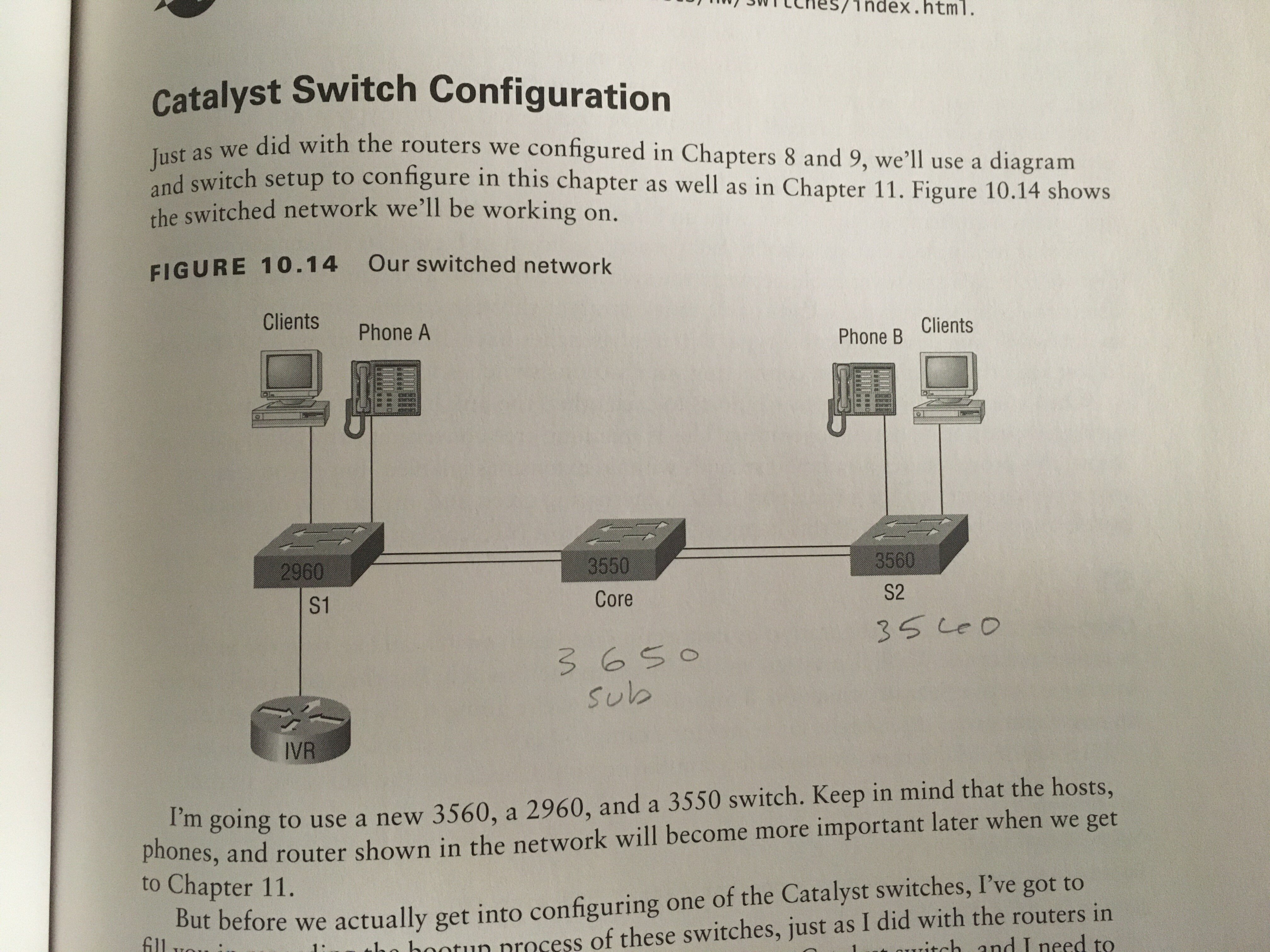
As noted, I am having to substitue different models. Packet Tracer 8.2 has these options:

Todd mentions that the 2960 and 3560 are 8-port models. Packet Tracer doesnt offer any 8-port models.
I tried to match the models as closely as possible.
2950 already matches (but not 8-port)
3650 sub for 3550
3560 already matches (but not 8-port)
I anticipated mismatched port numbers between the book's switches and packet tracer's, so I planned to make substitutions:
Device
Book Port
PKT Port
SW1
f0/1
f0/1
1st conn to Core
SW1
f0/2
f0/2
2nd conn to Core
SW1
f0/3
f0/3
to HostA
SW1
f0/4
f0/4
to PhoneA
SW1
f0/8
f0/8
to IVR
-------------------------------------------
SW2
fa0/1
f0/1
1st conn to Core
SW2
fa0/2
f0/2
2nd conn to Core
SW2
fa0/3
f0/3
to HostB
SW2
fa0/4
f0/4
to PhoneB
I havent had to change anything up to this point... but note that I programmed each interface using "f" instead of using "fa".
The book uses "f" and "fa", seemingly interchangeably.... I'll discuss this more in a moment...
Core switch:
Device
Book Port
PKT Port
Core
f0/5
g1/0/1
1st conn to SW2
Core
fa0/5
g1/0/2
2nd conn to SW2
Core
fa0/7
g1/0/3
1st conn to SW1
Core
fa0/8
g1/0/4
2nd conn to SW1
This got tricky because the interface labels are completely different.
I started to wonder.....
If I had been able to find a switch that used the same port names, and attempted to configure exactly as shown in the book,
wouldn't fa0/5 have overwritten f0/5... assuming the "A" is optional and each command is interchangeable?
After some research, I am satisfied that there is actually no difference between 'F' and 'FA'.

Reference
And I started thinking, could this be a typo in the book. So I referred back to the Wiley site, where I have already
identified one typo that had me confused, earlier in the book.
Sure enough, this is a mistake:
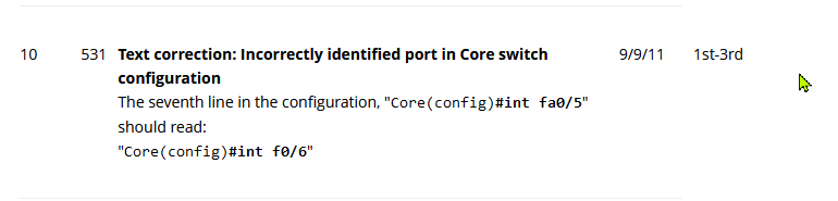
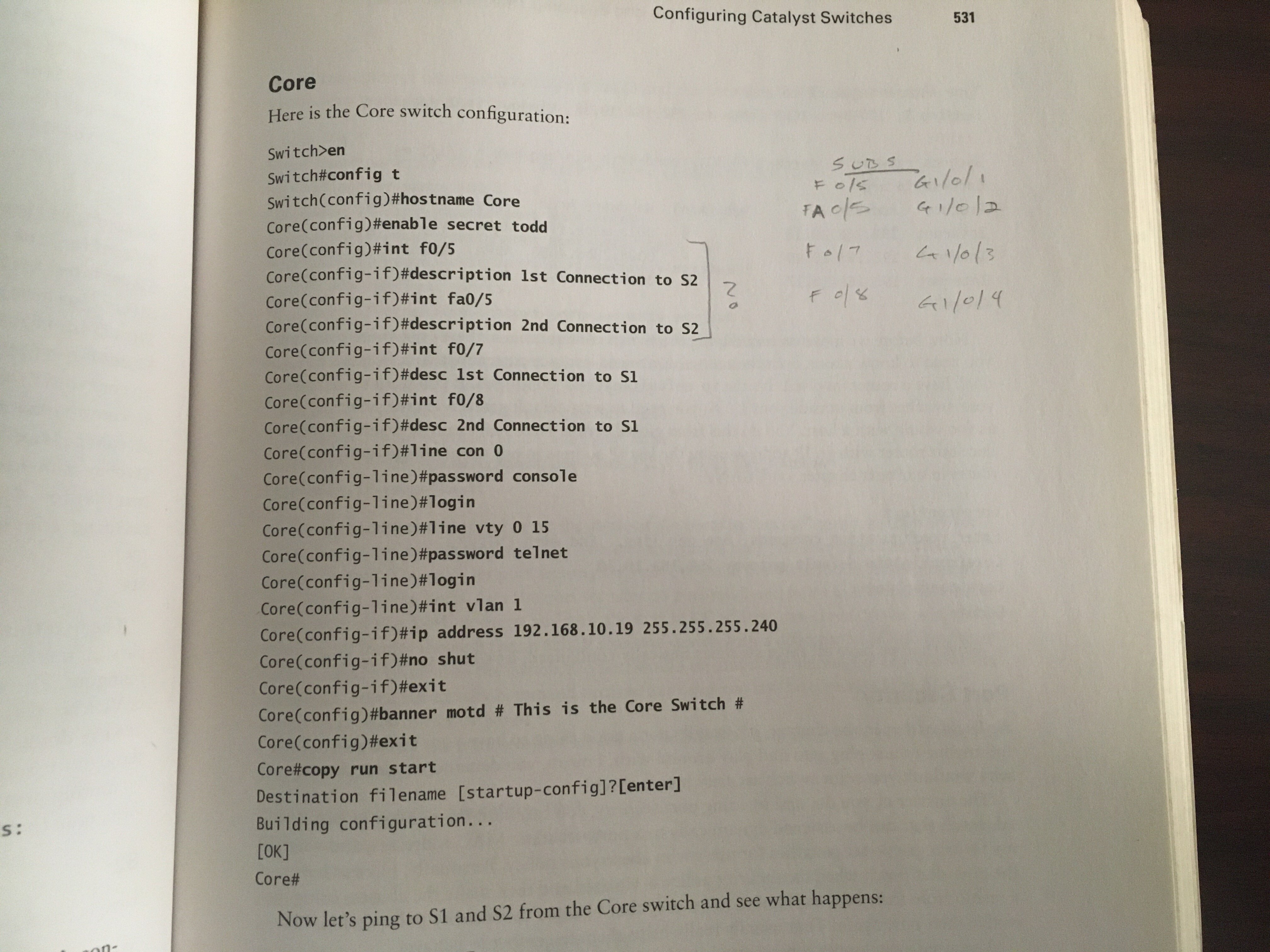
Still doesnt quite explain why he was using exclusively "FA" on SwitchA, then "F" on SwitchB and Core. Maybe to prove a point, that they
are interchangeable. I couldn't find anything that suggests it matters which is used.
Interestingly:
I discovered a new command through this investigation.
Since show ip int brief gives you
the full interface name, but doesnt show the "official" abbreviated versions.
Interface              IP-Address      OK? Method Status                Protocol
GigabitEthernet1/0/1   unassigned      YES unset  down                  down
GigabitEthernet1/0/2   unassigned      YES unset  down                  down
GigabitEthernet1/0/3   unassigned      YES unset  down                  down
GigabitEthernet1/0/4   unassigned      YES unset  down                  down
I found that show int status shows the ABBREVIATIONS used
on the device. I checked on several devices, and this helped convince me that there is "no such thing" as
an "F" interface vs an "FA" interface.. other than being a shorthand equivalent.
To access the the 4 interfaces below, we could use "Gig", "Gi" or just "G"
Port      Name               Status       Vlan       Duplex  Speed Type
Gig1/0/1  1st conn to SW2    notconnect   1          auto    auto  10/100BaseTX
Gig1/0/2  2nd conn to SW2    notconnect   1          auto    auto  10/100BaseTX
Gig1/0/3  1st connection to  notconnect   1          auto    auto  10/100BaseTX
Gig1/0/4  2nd connection to  notconnect   1          auto    auto  10/100BaseTX/span>
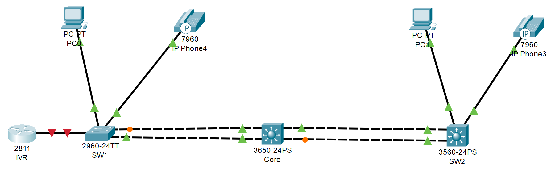
The topology is built out

SW1#
show interface status
Port      Name               Status       Vlan       Duplex  Speed Type
Fa0/1     1st connection to  connected    1          auto    auto  10/100BaseTX
Fa0/2     2nd connection to  connected    1          auto    auto  10/100BaseTX
Fa0/3     connection to Host connected    1          auto    auto  10/100BaseTX
Fa0/4     connection to Phon connected    1          auto    auto  10/100BaseTX
Fa0/5                        notconnect   1          auto    auto  10/100BaseTX
Fa0/6                        notconnect   1          auto    auto  10/100BaseTX
Fa0/7                        notconnect   1          auto    auto  10/100BaseTX
Fa0/8     connection to IVR  notconnect   1          auto    auto  10/100BaseTX
Core#
show interface status
Gig1/0/1  1st conn to SW2    connected    1          auto    auto  10/100BaseTX
Gig1/0/2  2nd conn to SW2    connected    1          auto    auto  10/100BaseTX
Gig1/0/3  1st connection to  connected    1          auto    auto  10/100BaseTX
Gig1/0/4  2nd connection to  connected    1          auto    auto  10/100BaseTX
SW2#
show interface status
Fa0/1     1st connection to  connected    1          auto    auto  10/100BaseTX
Fa0/2     2nd connection to  connected    1          auto    auto  10/100BaseTX
Fa0/3     connection to Host connected    1          auto    auto  10/100BaseTX
Fa0/4     connection to Phon connected    1          auto    auto  10/100BaseTX
IVR#
show interface status
output
Test pings...
Ping from S2 to S1, going through Corp
SW2#
ping 192.168.10.17
Sending 5, 100-byte ICMP Echos to 192.168.10.17, timeout is 2 seconds:
..!!!
Success rate is 60 percent (3/5), round-trip min/avg/max = 0/0/1 ms
REPEAT Ping from S2 to S1, going through Corp
SW2#
ping 192.168.10.17
Sending 5, 100-byte ICMP Echos to 192.168.10.17, timeout is 2 seconds:
!!!!!
Success rate is 100 percent (5/5), round-trip min/avg/max = 0/0/2 ms
From Core, Ping SW1
Core#
ping 192.168.10.17
Sending 5, 100-byte ICMP Echos to 192.168.10.17, timeout is 2 seconds:
..!!!
Success rate is 60 percent (3/5), round-trip min/avg/max = 0/0/0 ms
From Core, Ping SW2
Core#
ping 192.168.10.17
Sending 5, 100-byte ICMP Echos to 192.168.10.18, timeout is 2 seconds:
.!!!!
Success rate is 80 percent (4/5), round-trip min/avg/max = 0/0/0 ms
REPEAT From Core, Ping SW1
Core#
ping 192.168.10.17
Sending 5, 100-byte ICMP Echos to 192.168.10.17, timeout is 2 seconds:
!!!!!
Success rate is 100 percent (5/5), round-trip min/avg/max = 0/0/2 ms
REPEAT From Core, Ping SW2
Core#
ping 192.168.10.17
Sending 5, 100-byte ICMP Echos to 192.168.10.18, timeout is 2 seconds:
!!!!!
Success rate is 100 percent (5/5), round-trip min/avg/max = 0/0/1 ms
Port Security
SW1(config)#
int range f0/3 - 4
SW1(config-if-range)#
switchport mode access
Default port mode is "desirable"-- meaning they will trunk if they are connected to another switch.
You cannot set port security on a port in desirable mode, so we set the port to Access mode
SW1(config-if-range)#
switchport port-security
enables security
SW1(config-if-range)#
switchport port-security maximum ?
<1-132> Maximum addresses
SW1(config-if-range)#
switchport port-security maximum 1
max of 1 mac allowed
SW1(config-if-range)#
switchport port-security mac-address sticky
only the first MAC will be allowed to send frames
SW1(config-if-range)#
switchport port-security violation ?
  <1-132>   protect   Security violation protect mode
  restrict  Security violation restrict mode
  shutdown  Security violation shutdown mode
SW1(config-if-range)#
switchport port-security violation shutdown
if a second MAC connects, the port will be shut down
SW1#
show port-security
<1-132>
Secure Port MaxSecureAddr CurrentAddr SecurityViolation Security Action
               (Count)       (Count)        (Count)
--------------------------------------------------------------------
        Fa0/3        1          0                 0         Shutdown
        Fa0/4        1          0                 0         Shutdown
----------------------------------------------------------------------
SW1#
show port-security interface f0/3
<1-132>
% Invalid input detected at '^' marker.

SW1#show port-security interface f0/3
Port Security              : Enabled
Port Status                : Secure-up
Violation Mode             : Shutdown
Aging Time                 : 0 mins
Aging Type                 : Absolute
SecureStatic Address Aging : Disabled
Maximum MAC Addresses      : 1
Total MAC Addresses        : 0
Configured MAC Addresses   : 0
Sticky MAC Addresses       : 0
Last Source Address:Vlan   : 0000.0000.0000:0
Security Violation Count   : 0
Two alternative violation modes to shutdown:
Protect- another host can connect, but frames will be dropped
Restrict- alerts via SNMP that a violation has occurred on the port
PortFast, UplinkFast, and BackboneFast
SW1#(config)
int range f0/3 - 4
SW1#(config-if-range)
spanning-tree portfast ?
  disable  Disable portfast for this interface
  trunk    Enable portfast on the interface even in trunk mode
SW1#(config-if-range)
spanning-tree portfast
%Warning: portfast should only be enabled on ports connected to a single
host. Connecting hubs, concentrators, switches, bridges, etc... to this
interface  when portfast is enabled, can cause temporary bridging loops.
Use with CAUTION

%Portfast has been configured on FastEthernet0/3 but will only
have effect when the interface is in a non-trunking mode.
%Warning: portfast should only be enabled on ports connected to a single
host. Connecting hubs, concentrators, switches, bridges, etc... to this
interface  when portfast is enabled, can cause temporary bridging loops.
Use with CAUTION

%Portfast has been configured on FastEthernet0/4 but will only
have effect when the interface is in a non-trunking mode.
SW1#(config-if-range)
spanning-tree bpduguard enable
The next few commands from book are N/A in Packet Tracer
SW1#(config-if)
spanning-tree ?
  bpduguard  Don't accept BPDUs on this interface
  cost       Change an interface's spanning tree port path cost
  guard      Change an interface's spanning tree guard mode
  link-type  Specify a link type for spanning tree protocol use
  portfast   Enable an interface to move directly to forwarding on link up
  vlan       VLAN Switch Spanning Tree
SW1#(config)
spanning-tree uplinkfast N/A
SW1#(config)
do show spanning-tree uplinkfast N/A
SW1#(config)
do show spanning-tree mode rapid-pvst N/A
SW2#(config)
int range f0/3 - 4
SW2#(config-if-range)
spanning-tree portfast ?
  disable  Disable portfast for this interface
  trunk    Enable portfast on the interface even in trunk mode
SW2#(config-if-range)
spanning-tree portfast
%Warning: portfast should only be enabled on ports connected to a single
host. Connecting hubs, concentrators, switches, bridges, etc... to this
interface  when portfast is enabled, can cause temporary bridging loops.
Use with CAUTION

%Portfast has been configured on FastEthernet0/3 but will only
have effect when the interface is in a non-trunking mode.
%Warning: portfast should only be enabled on ports connected to a single
host. Connecting hubs, concentrators, switches, bridges, etc... to this
interface  when portfast is enabled, can cause temporary bridging loops.
Use with CAUTION

%Portfast has been configured on FastEthernet0/4 but will only
have effect when the interface is in a non-trunking mode.
SW2#(config-if-range)
spanning-tree bpduguard enable
The next few commands from book are N/A in Packet Tracer
SW2#(config-if)
spanning-tree ?
  bpduguard  Don't accept BPDUs on this interface
  cost       Change an interface's spanning tree port path cost
  guard      Change an interface's spanning tree guard mode
  link-type  Specify a link type for spanning tree protocol use
  portfast   Enable an interface to move directly to forwarding on link up
  vlan       VLAN Switch Spanning Tree
SW2#(config)
spanning-tree uplinkfast N/A
SW2#(config)
do show spanning-tree uplinkfast N/A
SW2#(config)
do show spanning-tree mode rapid-pvst N/A
 Reference
Review status of each switch
SW1#
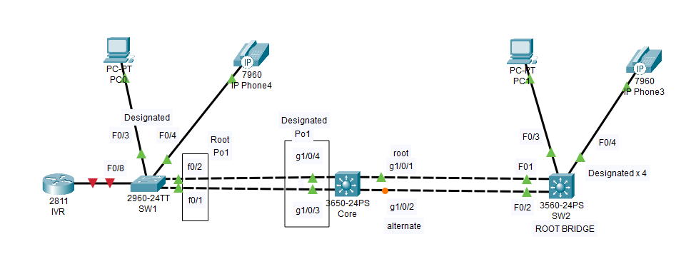
show spanning-tree
VLAN0001
  Spanning tree enabled protocol ieee
  Root ID    Priority    32769
             Address     0001.645B.5321
             Cost        38
             Port        1(FastEthernet0/1)
             Hello Time  2 sec  Max Age 20 sec  Forward Delay 15 sec

  Bridge ID  Priority    32769  (priority 32768 sys-id-ext 1)
             Address     00E0.F7BC.472E
             Hello Time  2 sec  Max Age 20 sec  Forward Delay 15 sec
             Aging Time  20

Interface        Role Sts Cost      Prio.Nbr Type
---------------- ---- --- --------- -------- --------------------------------
Fa0/1            Root FWD 19        128.1    P2p
Fa0/2            Altn BLK 19        128.2    P2p
Fa0/3            Desg FWD 19        128.3    P2p
Fa0/4            Desg FWD 19        128.4    P2p
SW2#
show spanning-tree
VLAN0001
  Spanning tree enabled protocol ieee
  Root ID    Priority    32769
             Address     0001.645B.5321
             This bridge is the root
             Hello Time  2 sec  Max Age 20 sec  Forward Delay 15 sec

  Bridge ID  Priority    32769  (priority 32768 sys-id-ext 1)
             Address     0001.645B.5321
             Hello Time  2 sec  Max Age 20 sec  Forward Delay 15 sec
             Aging Time  20

Interface        Role Sts Cost      Prio.Nbr Type
---------------- ---- --- --------- -------- --------------------------------
Fa0/1            Desg FWD 19        128.1    P2p
Fa0/3            Desg FWD 19        128.3    P2p
Fa0/2            Desg FWD 19        128.2    P2p
Fa0/4            Desg FWD 19        128.4    P2p
Core#
show spanning-tree
VLAN0001
  Spanning tree enabled protocol ieee
  Root ID    Priority    32769
             Address     0001.645B.5321
             Cost        19
             Port        1(GigabitEthernet1/0/1)
             Hello Time  2 sec  Max Age 20 sec  Forward Delay 15 sec

  Bridge ID  Priority    32769  (priority 32768 sys-id-ext 1)
             Address     0001.96B3.31BC
             Hello Time  2 sec  Max Age 20 sec  Forward Delay 15 sec
             Aging Time  20

Interface        Role Sts Cost      Prio.Nbr Type
---------------- ---- --- --------- -------- --------------------------------
Gi1/0/1          Root FWD 19        128.1    P2p
Gi1/0/2          Altn BLK 19        128.2    P2p
Gi1/0/4          Desg FWD 19        128.4    P2p
Gi1/0/3          Desg FWD 19        128.3    P2p
Etherchannel
SW1(config)#
int port-channel 1
SW1(config-if)#
int range f0/1-2
SW1(config-if-range)#
switchport mode trunk
SW1(config-if-range)#
switchport nonegotiate
SW1(config-if-range)#
channel-group 1 mode desirable
%LINEPROTO-5-UPDOWN: Line protocol on Interface
FastEthernet0/1, changed state to down

%LINEPROTO-5-UPDOWN: Line protocol on Interface
FastEthernet0/1, changed state to up

%LINEPROTO-5-UPDOWN: Line protocol on Interface
FastEthernet0/2, changed state to down

%LINEPROTO-5-UPDOWN: Line protocol on Interface
FastEthernet0/2, changed state to up
SW1#
show interface etherchannel
----
FastEthernet0/1:
Port state    = 1
Channel group = 1           Mode = Desirable-S1    Gcchange = 0
Port-channel  = Po1         GC   = 0x00000000      Pseudo port-channel = Po1
Port index    = 0           Load = 0x00            Protocol =   PAgP

Flags:  S - Device is sending Slow hello.  C - Device is in Consistent state.
        A - Device is in Auto mode.        P - Device learns on physical port.
        d - PAgP is down.
Timers: H - Hello timer is running.        Q - Quit timer is running.
        S - Switching timer is running.    I - Interface timer is running.

Local information:
                                Hello    Partner  PAgP     Learning  Group
Port      Flags State   Timers  Interval Count   Priority   Method  Ifindex
Fa0/1     d     U1/S1   H30s    1        0        128        Any      0

Age of the port in the current state:  00d:00h:00m:00s

----
FastEthernet0/2:
Port state    = 1
Channel group = 1           Mode = Desirable-S1    Gcchange = 0
Port-channel  = Po1         GC   = 0x00000000      Pseudo port-channel = Po1
Port index    = 0           Load = 0x00            Protocol =   PAgP

Flags:  S - Device is sending Slow hello.  C - Device is in Consistent state.
        A - Device is in Auto mode.        P - Device learns on physical port.
        d - PAgP is down.
Timers: H - Hello timer is running.        Q - Quit timer is running.
        S - Switching timer is running.    I - Interface timer is running.

Local information:
                                Hello    Partner  PAgP     Learning  Group
Port      Flags State   Timers  Interval Count   Priority   Method  Ifindex
Fa0/2     d     U1/S1   H30s    1        0        128        Any      0

Age of the port in the current state:  00d:00h:00m:00s

----
Port-channel1:Port-channel1
Age of the Port-channel   = 00d:00h:27m:57s
Logical slot/port   = 2/1             Number of ports = 0
GC                  = 0x00000000      HotStandBy port = null
Port state          =
Protocol            =   2
Port Security       = Disabled
Core(config)#
int port-channel 1
Core(config-if)#
int range g1/0/3-4
Core(config-if-range)#
switchport encap dot1q
% Interface range command failed for GigabitEthernet1/0/3
% Command failed on interface GigabitEthernet1/0/3. Aborting
The interfaces are failing to join the etherchannel..
alternate path:
Core(config)#
int range g1/0/3-4
Core(config-if-range)#
channel-group 1 mode on
%LINK-5-CHANGED: Interface Port-channel1, changed state to up

%LINEPROTO-5-UPDOWN: Line protocol on Interface Port-channel1, changed state to up
%PM-4-ERR_DISABLE: channel-misconfig error detected on Gig1/0/3, putting Gig1/0/3 in err-disable state

%LINK-3-UPDOWN: Interface GigabitEthernet1/0/3, changed state to down

%LINEPROTO-5-UPDOWN: Line protocol on Interface GigabitEthernet1/0/3, changed state to down

%LINEPROTO-5-UPDOWN: Line protocol on Interface Port-channel1, changed state to down
Core#
show etherchannel summary
Flags:  D - down        P - in port-channel
        I - stand-alone s - suspended
        H - Hot-standby (LACP only)
        R - Layer3      S - Layer2
        U - in use      f - failed to allocate aggregator
        u - unsuitable for bundling
        w - waiting to be aggregated
        d - default port


Number of channel-groups in use: 1
Number of aggregators:           1

Group  Port-channel  Protocol    Ports
------+-------------+-----------+----------------------------------------------

1      Po1(SD)           -      Gig1/0/3(D) Gig1/0/4(D)
Core(config)#
int port-channel 1
Core(config-if)#
switchport mode trunk
Core(config-if)#
int port-channel 1
Core(config-if)#
exit
Core(config)#
int range g1/0/3-4
Core(config-if-range)#
channel-group 1 mode desirable
CONFUSION
Ran into some trouble here. After a day of reserach, I have clarified the issue. I"m completely new to this subject, and the book is being a little vague.. I drew upon some additional resources- general google
research, and a couple of videos from Dancourses.
Here is some shorthand testing I did in excel to undestand the distinction between commands..
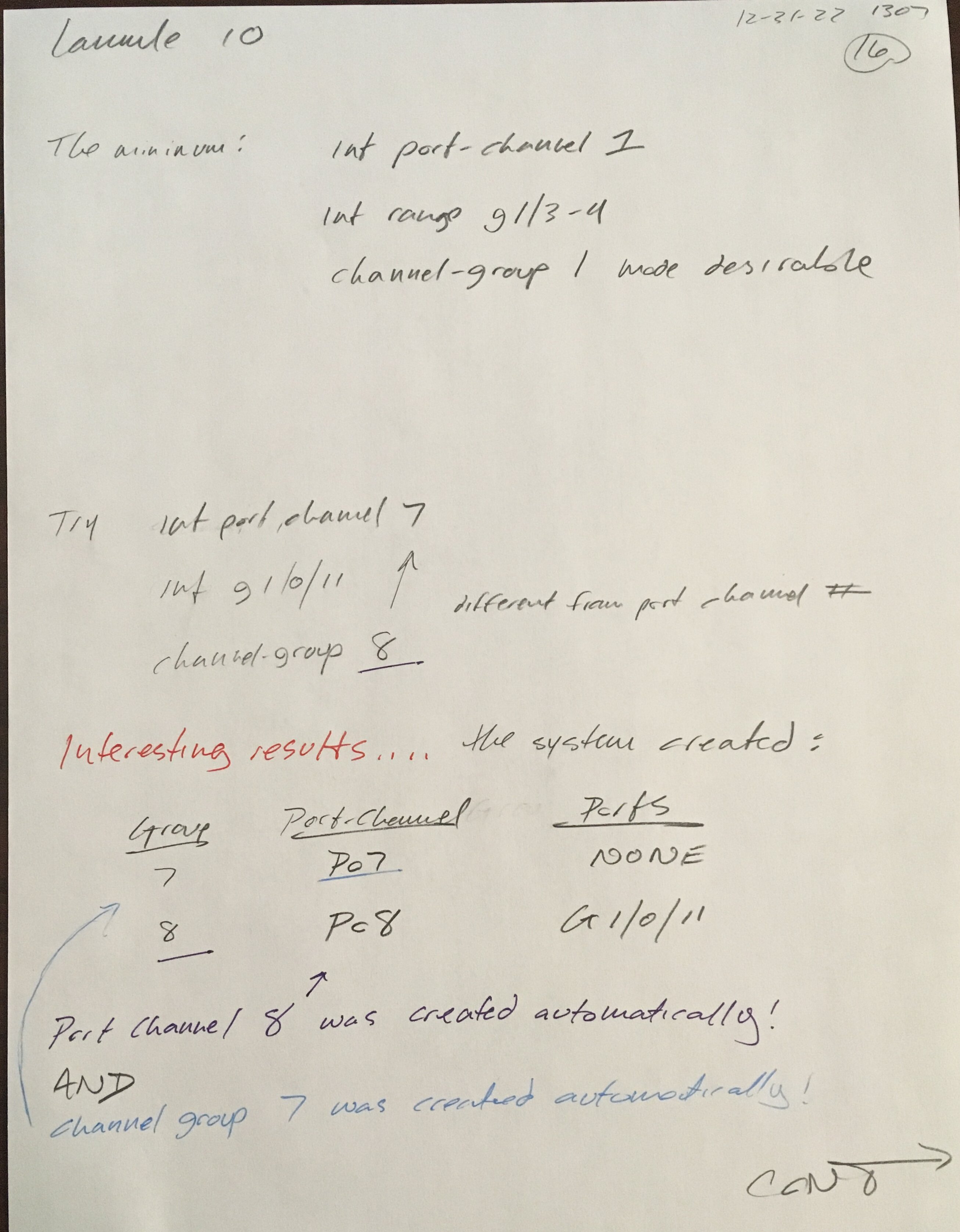
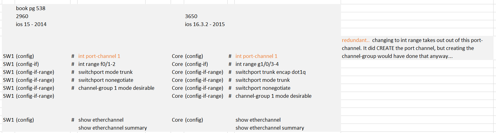
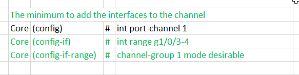
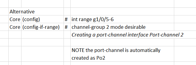
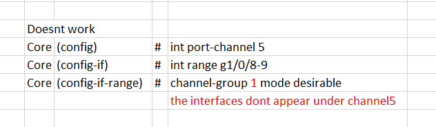
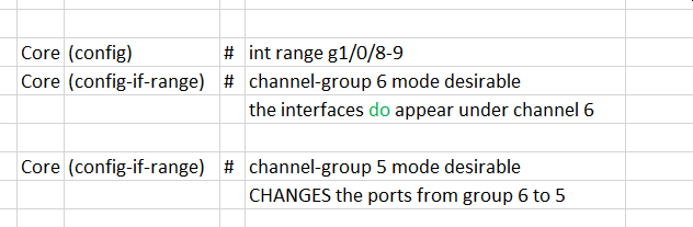

and after working through this lab, I am less confused...
Comparison:
Lammle 2011
int port-channel 1
int range f0/1-2
switchport mode trunk
switchport nonegotiate
channel-group 1 mode desirable
first command creates port channel 1.. but next command switches to interfaces f0/1-2
f0/1-2 are set as trunk
then inserted into "channel group 1"... being in the group associatees them with the virtual interface "channel 1", which would have been created without the first command; it's created when the group is created
DanCourses 2014
int range f0/1-2
channel-group 1 mode desirable
int port-channel 1
switchport mode trunk
f0/1-2 are set as trunk are inserted into "channel group 1", which also associates them with virtual interface "channel 1".
we change interfaces to "channel 1" set as trunk
Through experimentation I proved that the commands
int port-channel 1
int range f0/1-2
do NOT result in f0/1-2 being part of port-channel 1.
You are simply creating the port-channel 1, then switching away from it to f01-2
Going back to the Lammle Lab in Packet Tracer, we'll review the spanning-tree config after setting the etherchannel
SW1#
show etherchannel summary
Number of channel-groups in use: 1
Number of aggregators:           1

Group  Port-channel  Protocol    Ports
------+-------------+-----------+----------------------------------------------

1      Po1(SU)           PAgP   Fa0/1(P) Fa0/2(P)
Core#
show etherchannel summary
Number of channel-groups in use: 1
Number of aggregators:           1

Group  Port-channel  Protocol    Ports
------+-------------+-----------+----------------------------------------------

1      Po1(SU)           PAgP   Gig1/0/3(P) Gig1/0/4(P)
SW1#
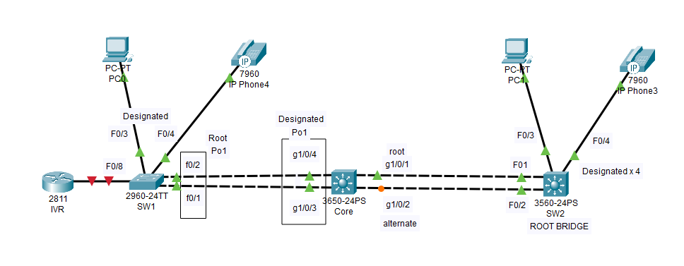
show spanning-tree
VLAN0001
  Spanning tree enabled protocol ieee
  Root ID    Priority    32769
             Address     0001.645B.5321
             Cost        28
             Port        27(Port-channel1)
             Hello Time  2 sec  Max Age 20 sec  Forward Delay 15 sec

  Bridge ID  Priority    32769  (priority 32768 sys-id-ext 1)
             Address     00E0.F7BC.472E
             Hello Time  2 sec  Max Age 20 sec  Forward Delay 15 sec
             Aging Time  20

Interface        Role Sts Cost      Prio.Nbr Type
---------------- ---- --- --------- -------- --------------------------------
Fa0/3            Desg FWD 19        128.3    P2p
Fa0/4            Desg FWD 19        128.4    P2p
Po1              Root FWD 9         128.27   Shr
Core#
show spanning-tree
VLAN0001
  Spanning tree enabled protocol ieee
  Root ID    Priority    32769
             Address     0001.645B.5321
             Cost        19
             Port        1(GigabitEthernet1/0/1)
             Hello Time  2 sec  Max Age 20 sec  Forward Delay 15 sec

  Bridge ID  Priority    32769  (priority 32768 sys-id-ext 1)
             Address     0001.96B3.31BC
             Hello Time  2 sec  Max Age 20 sec  Forward Delay 15 sec
             Aging Time  20

Interface        Role Sts Cost      Prio.Nbr Type
---------------- ---- --- --------- -------- --------------------------------
Gi1/0/1          Root FWD 19        128.1    P2p
Gi1/0/2          Altn BLK 19        128.2    P2p
Po1              Desg FWD 9         128.29   Shr
SW2#
show spanning-tree
VLAN0001
  Spanning tree enabled protocol ieee
  Root ID    Priority    32769
             Address     0001.645B.5321
             This bridge is the root
             Hello Time  2 sec  Max Age 20 sec  Forward Delay 15 sec

  Bridge ID  Priority    32769  (priority 32768 sys-id-ext 1)
             Address     0001.645B.5321
             Hello Time  2 sec  Max Age 20 sec  Forward Delay 15 sec
             Aging Time  20

Interface        Role Sts Cost      Prio.Nbr Type
---------------- ---- --- --------- -------- --------------------------------
Fa0/1            Desg FWD 19        128.1    P2p
Fa0/2            Desg FWD 19        128.2    P2p
Fa0/3            Desg FWD 19        128.3    P2p
Fa0/4            Desg FWD 19        128.4    P2p
Chapter 10, Layer 2 Switching and STP - Exam Essentials
1. Remember the three switch functions
address learning
forward/filter decisions
loop avoidance
2. Remember the command show mac address-table
shows the forward/filter table
3. Understand the main purpose of STP in a switched LAN
prevents loops among redundant switch paths.. but allows alternate paths to be used if needed
4. Remember the states of STP
BLOCKING
prevent use of the path
LISTENING
prepare to forward frames, without populating the MAC table
LEARNING
populate the MAC table, but dont forward frames
FORWARDING
sends and receives all frames
DISABLED
non operational
5. Remember the command show spanning-tree
shows port statuses and who root bridge is
Chapter 10, Layer 2 Switching and STP - Written Lab 10.0
1. What command will show you the forward/filter table?
show mac address-table
2. If a destination MAC address is not in the forward/filter table,
what will the switch do with the frame?
flood the frame from all ports execept the receiving port
3. What are the three switch functions at Layer 2?
address learning
forwarding/filtering
loop management
4. If a frame is received on a switch port and the source MAC address is not in the forward/filter
table, what will the switch do?
add the source Mac to the table
5. Which proprietary Cisco STP extension would put a switch port into err-disabled if a BPDU is
received on this port?
BPDU Guard- places the port into err disabled state if it is in Portfast mode and a BPDU is received.. Shoulndt happen bc BPDUGUard is set on
ports that dont lead to other switches.. minimizes delays associated w/STP conergence
Related:
BPDU Filter - stops BPDU's from coming/going on a port. Will immediately remove a port from Portfast and put the port back into STP topology
STP Extensions:
Portfast - for ports leading to clients... If a port is enabled with Portfast, you need BPDUGuard to prevent accidental conection of another switch.
UplinkFast -
BackboneFast
Rapid STP 802.1W
6. 802.1w is also called what?
Rapid STP
(original STP was 802.1D)
802.1D, 802.1W, and 802.1S(multiple spanning tree) are now all combined into 802.1Q-2014
7. When is STP considered to be "converged"?
all ports are in either BLOCKING or FORWARDING
8. Switches break up ___________ domains.
COLLISION
9. What is used to prevent switching loops in a network with redundant switched paths?
STP
10. Which Cisco 802.1d extension stops BPDU from being transmitted out a port?
PORTFAST
for ports leading to clients... Then use BPDUGuard to prevent accidental conection of another switch.
Chapter 10, Layer 2 Switching and STP - Review
1. Which is a layer 2 protocol used to maintain a loop-free network?
STP
2. What command will display the forward/filter table?
show mac address-table
3. What is the result of segmenting a network with a bridge(switch)?
INCREASES the number of collision domains... one for each switch port
AND
makes smaller collision domains
4. Which statement describes a spanning-tree network that has converged?
all ports are either FORWARDING or BLOCKING... note that even root ports will be in one of these states
5. What is the purpose of STP in a switched LAN?
prevent loops among redundant paths
6. What are the three distinct functions of layer 2 switching that
increase available bandwidth on the network?
address learning, forwarding/filtering, loop avoidance
7. Your switch has a port status LED that is alternating between green and amber. What could
this indicate?
The port could be experiencing errors.. At first connect the light should be orange, but then should turn SOLID GREEN
8. Which is true about collision/broadcast?
a switch creates seperate collision domains, but only one broadcast domain
a router provides a seperate broadcast domain
9. You need to configure a Catalyst switch so it can be managed remotely. Which commmands to use?
ip default-gateway 192.168.10.254
int vlan 1
ip addr 192.168.10.252 255.255.255.0
no shut
DONT FORGET NO SHUT
ip default gateway is needed to point to router. NOTE that we arent giving an IP to a switchport.. but to a VLAN on the switch
10. What does a switch do when a frame is received on an interface and the destination hardware address
is unknown or not in the filter table?
flood the frame from all ports execpt the receiving port
11. If a switch receives a frame and the source MAC address is not in the MAC address
table but the destination address is, what will the switch do with the frame?
save the source MAC to table, then send the frame to known destination address
12. You want to run the new 802.1w on your switches. Which command would enable the protocol?
spanning-tree mode rapid-pvst
spanning-tree mode ?
  pvst        Per-Vlan spanning tree mode
  rapid-pvst  Per-Vlan rapid spanning tree mode
13. In which circumstance are multiple copies of the same
unicast frame likely to be transmitted in a switched LAN?
improperly implemented redundant topology
14. Which command was used to produce this output:

show mac address-table
15. Which command to disable STP on a port connected to a server
spanning-tree portfast
spanning-tree ?
  mode      Spanning tree operating mode
  portfast  Spanning tree portfast options
  vlan      VLAN Switch Spanning Tree
16.Why does the switch have two MAC addresses assigned to F0/1?
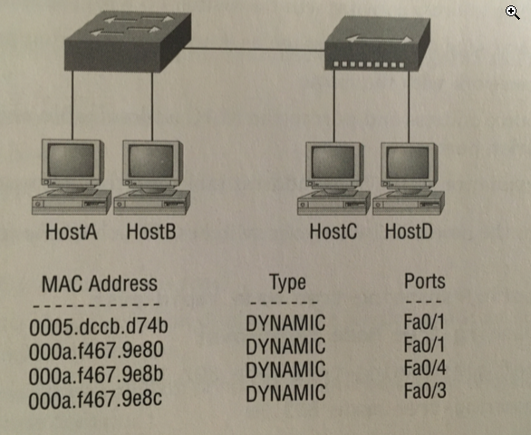
a HUB must be connected to f0/1. A switch CAN have multiple MACs for a port
17. Layer 2 switching provides:
hardware-based bridging (ASIC)
wire speed
low latency
low cost
18. You type show mac address-table and get this output:

What will the switch do if it receives a frame with
source MAC: 0005.dccb.d74b
des MAC: 000a.f467.9e8c
the switch recognizes both MACs... will send out Fa0/3 only
19. You need to allow one host to be permitted to attach dynamically to each switch interface.
Which two commands are needed?
switchport port-security maximum 1
switchport port-security violation shutdown
running this on EACH port allows one mac to attach (and re-attach) to the port... if another tries, port disables
20. You have two switches connected together with two crossover cables for redundancy, and
STP is disabled. What will happen between the switches?
loops, broadcast storms will occur between the two links... among other possible issues
NOTE that STP helps with:
redundant links between two switches
and
redundant pathways from switch to switch in a network of many switches
----------------------------------------------------------
End Chapter 10
25 hours 12-28 thru 12-31-2022
book running total 255 hours
book page 556/822
255 hours * 60 = 15300 min / 556 pages
28 min/page (includes reading, exercises/labs + online research)
Chapter 11, VLANs - Exercises
SW1(config)#
vlan 2
SW1(config-vlan)#
name Sales
SW1(config-vlan)#
vlan 3
SW1(config-vlan)#
name Marketing
SW1(config-vlan)#
vlan 4
SW1(config-vlan)#
name Accounting
Output at right: Note that F0/1 and F0/2 are not displayed------------->
but we can see them here:
SW1#
show etherchannel summary
Number of channel-groups in use: 1
Number of aggregators:           1

Group  Port-channel  Protocol    Ports
------+-------------+-----------+----------------------------------------------

1      Po1(SU)           PAgP   Fa0/1(P) Fa0/2(P)
Any port that is a trunk port will not show up in the VLAN database....
We put port-channel 1 into trunk mode earlier. There is a seperate command to see trunk ports.
SW1#
show interface ?
  Ethernet         IEEE 802.3
  FastEthernet     FastEthernet IEEE 802.3
  GigabitEthernet  GigabitEthernet IEEE 802.3z
  Port-channel     Ethernet channel port interface
  Vlan             Catalyst Vlans
  etherchannel     Show interface etherchannel information
  status           interface line status
  switchport       Show interface switchport information
  trunk            Show interface trunk information
  |                Output Modifiers
SW1#
show interface trunk
  Port        Mode         Encapsulation  Status        Native vlan
Po1         on           802.1q         trunking      1

Port        Vlans allowed on trunk
Po1         1-1005

Port        Vlans allowed and active in management domain
Po1         1,2,3,4

Port        Vlans in spanning tree forwarding state and not pruned
Po1         1,2,3,4
SW1#
show vlan
VLAN Name                             Status    Ports
---- -------------------------------- --------- -------------------------------
1    default                          active    Fa0/3, Fa0/4, Fa0/5, Fa0/6
                                                Fa0/7, Fa0/8, Fa0/9, Fa0/10
                                                Fa0/11, Fa0/12, Fa0/13, Fa0/14
                                                Fa0/15, Fa0/16, Fa0/17, Fa0/18
                                                Fa0/19, Fa0/20, Fa0/21, Fa0/22
                                                Fa0/23, Fa0/24, Gig0/1, Gig0/2
2    Sales                            active
3    Marketing                        active
4    Accounting                       active
1002 fddi-default                     active
1003 token-ring-default               active
1004 fddinet-default                  active
1005 trnet-default                    active

VLAN Type  SAID       MTU   Parent RingNo BridgeNo Stp  BrdgMode Trans1 Trans2
---- ----- ---------- ----- ------ ------ -------- ---- -------- ------ ------
1    enet  100001     1500  -      -      -        -    -        0      0
2    enet  100002     1500  -      -      -        -    -        0      0
3    enet  100003     1500  -      -      -        -    -        0      0
4    enet  100004     1500  -      -      -        -    -        0      0
1002 fddi  101002     1500  -      -      -        -    -        0      0
1003 tr    101003     1500  -      -      -        -    -        0      0
1004 fdnet 101004     1500  -      -      -        ieee -        0      0
1005 trnet 101005     1500  -      -      -        ibm  -        0      0

VLAN Type  SAID       MTU   Parent RingNo BridgeNo Stp  BrdgMode Trans1 Trans2
---- ----- ---------- ----- ------ ------ -------- ---- -------- ------ ------

Remote SPAN VLANs
------------------------------------------------------------------------------

Primary Secondary Type              Ports
------- --------- ----------------- ------------------------------------------
Now we'll assign switchports to VLANs on SW1 model 2960 (runs 802.1q only)
Each port can be part of only one VLAN (except voice access ports)
SW1(config)#
int f0/3
SW1(config-if)#
switchport mode access
SW1(config-if)#
switchport access vlan 3
SW1(config)#
int f0/8
SW1(config-if)#
switchport mode trunk
Prompt#
command
output
Core switch model 3560 (layer 3 switch, can run ISL and 802.1q)
Core#
show etherchannel summary
Number of channel-groups in use: 1
Number of aggregators:           1

Group  Port-channel  Protocol    Ports
------+-------------+-----------+----------------------------------------------

1      Po1(SU)           PAgP   Gig1/0/3(P) Gig1/0/4(P)
Core#
show interface trunk
Port        Mode         Encapsulation  Status        Native vlan
Po1         on           802.1q         trunking      1

Port        Vlans allowed on trunk
Po1         1-1005

Port        Vlans allowed and active in management domain
Po1         1

Port        Vlans in spanning tree forwarding state and not pruned
Po1         1
Core#
show vlan
VLAN Name                             Status    Ports
---- -------------------------------- --------- -------------------------------
1    default                          active    Gig1/0/1, Gig1/0/2, Gig1/0/5, Gig1/0/6
                                                Gig1/0/7, Gig1/0/8, Gig1/0/9, Gig1/0/10
                                                Gig1/0/11, Gig1/0/12, Gig1/0/13, Gig1/0/14
                                                Gig1/0/15, Gig1/0/16, Gig1/0/17, Gig1/0/18
                                                Gig1/0/19, Gig1/0/20, Gig1/0/21, Gig1/0/22
                                                Gig1/0/23, Gig1/0/24, Gig1/1/1, Gig1/1/2
                                                Gig1/1/3, Gig1/1/4
1002 fddi-default                     active
1003 token-ring-default               active
1004 fddinet-default                  active
1005 trnet-default                    active

VLAN Type  SAID       MTU   Parent RingNo BridgeNo Stp  BrdgMode Trans1 Trans2
---- ----- ---------- ----- ------ ------ -------- ---- -------- ------ ------
1    enet  100001     1500  -      -      -        -    -        0      0
1002 fddi  101002     1500  -      -      -        -    -        0      0
1003 tr    101003     1500  -      -      -        -    -        0      0
1004 fdnet 101004     1500  -      -      -        ieee -        0      0
1005 trnet 101005     1500  -      -      -        ibm  -        0      0

VLAN Type  SAID       MTU   Parent RingNo BridgeNo Stp  BrdgMode Trans1 Trans2
---- ----- ---------- ----- ------ ------ -------- ---- -------- ------ ------

Remote SPAN VLANs
------------------------------------------------------------------------------

Primary Secondary Type              Ports
------- --------- ----------------- ------------------------------------------
Definiing the allowed vlans on a trunk
SW1(config)#
int f0/1 (this interface is part of Port-Channel 1)
SW1(config-if)#
switchport trunk allowed vlan remove 4
The trunk link on f0/1 will drop all traffic sent/received for VLAN4
SW1#
show run[cut]
interface FastEthernet0/1
description 1st connection to core switch
switchport trunk allowed vlan 1-3,5-1005
switchport mode trunk
switchport nonegotiate
channel-group 1 mode desirable
[cut]
Configuring VTP - first check statuses. All is default
SW1#
show vtp status
VTP Version capable : 1 to 2
VTP version running : 1
VTP Domain Name :
VTP Pruning Mode : Disabled
VTP Traps Generation : Disabled
Device ID : 0000.0C44.7800
Configuration last modified by 192.168.10.17 at 3-1-93 00:24:14
Local updater ID is 192.168.10.17 on interface Vl1 (lowest numbered VLAN interface found)
Feature VLAN :
--------------
VTP Operating Mode : Server
Maximum VLANs supported locally : 255
Number of existing VLANs : 8
Configuration Revision : 6
MD5 digest : 0xC9 0xA8 0x18 0xDA 0x81 0xAB 0xB6 0x18
0x94 0xA8 0x20 0xAC 0x83 0x54 0x11 0x13
Core#
show vtp status
VTP Version capable : 1 to 2
VTP version running : 1
VTP Domain Name :
VTP Pruning Mode : Disabled
VTP Traps Generation : Disabled
Device ID : 0000.0C47.E300
Configuration last modified by 0.0.0.0 at 0-0-00 00:00:00
Local updater ID is 192.168.10.19 on interface Vl1 (lowest numbered VLAN interface found)
Feature VLAN :
--------------
VTP Operating Mode : Server
Maximum VLANs supported locally : 1005
Number of existing VLANs : 5
Configuration Revision : 0
MD5 digest : 0x7D 0x5A 0xA6 0x0E 0x9A 0x72 0xA0 0x3A
0xF0 0x58 0x10 0x6C 0x9C 0x0F 0xA0 0xF7
SW2#
show vtp status
VTP Version capable : 1 to 2
VTP version running : 1
VTP Domain Name :
VTP Pruning Mode : Disabled
VTP Traps Generation : Disabled
Device ID : 000A.41A7.2600
Configuration last modified by 0.0.0.0 at 0-0-00 00:00:00
Local updater ID is 192.168.10.18 on interface Vl1 (lowest numbered VLAN interface found)
Feature VLAN :
--------------
VTP Operating Mode : Server
Maximum VLANs supported locally : 1005
Number of existing VLANs : 5
Configuration Revision : 0
MD5 digest : 0x7D 0x5A 0xA6 0x0E 0x9A 0x72 0xA0 0x3A
0xF0 0x58 0x10 0x6C 0x9C 0x0F 0xA0 0xF7
Config Client and Servers
SW1(config)#
vtp mode server
Device mode already VTP SERVER.
SW1(config)#
vtp domain lammle
Changing VTP domain name from NULL to lammle
SW1(config)#
vtp password todd
Setting device VLAN database password to todd
Core#
vtp mode client
Setting device to VTP CLIENT mode.
Core#
vtp domain lammle
Changing VTP domain name from NULL to lammle
Core#
vtp password todd
Setting device VLAN database password to todd
SW2#
vtp mode client
Setting device to VTP CLIENT mode.
SW2#
vtp domain lammle
Changing VTP domain name from NULL to lammle
SW2#
vtp password todd
Setting device VLAN database password to todd
Check statuses again
SW1#
show vtp status
VTP Version capable : 1 to 2
VTP version running : 1
VTP Domain Name : lammle
VTP Pruning Mode : Disabled
VTP Traps Generation : Disabled
Device ID : 0000.0C44.7800
Configuration last modified by 192.168.10.17 at 3-1-93 00:24:14
Local updater ID is 192.168.10.17 on interface Vl1 (lowest numbered VLAN interface found)
Feature VLAN :
--------------
VTP Operating Mode : Server
Maximum VLANs supported locally : 255
Number of existing VLANs : 8
Configuration Revision : 0
MD5 digest : 0x41 0x79 0xCD 0x08 0x50 0x87 0x28 0x33
0xC9 0x04 0xFD 0xF8 0x0A 0xF5 0xD8 0x0B
Core#
show vtp status
VTP Version capable : 1 to 2
VTP version running : 1
VTP Domain Name : lammle
VTP Pruning Mode : Disabled
VTP Traps Generation : Disabled
Device ID : 0000.0C47.E300
Configuration last modified by 192.168.10.17 at 3-1-93 00:24:14
Feature VLAN :
--------------
VTP Operating Mode : Client
Maximum VLANs supported locally : 1005
Number of existing VLANs : 8
Configuration Revision : 0
MD5 digest : 0x41 0x79 0xCD 0x08 0x50 0x87 0x28 0x33
0xC9 0x04 0xFD 0xF8 0x0A 0xF5 0xD8 0x0B
SW2#
show vtp status
VTP Version capable : 1 to 2
VTP version running : 1
VTP Domain Name : lammle
VTP Pruning Mode : Disabled
VTP Traps Generation : Disabled
Device ID : 0000.0C44.7800
Configuration last modified by 192.168.10.17 at 3-1-93 00:24:14
Feature VLAN :
--------------
VTP Operating Mode : Client
Maximum VLANs supported locally : 255
Number of existing VLANs : 8
Configuration Revision : 0
MD5 digest : 0x41 0x79 0xCD 0x08 0x50 0x87 0x28 0x33
0xC9 0x04 0xFD 0xF8 0x0A 0xF5 0xD8 0x0B
The vlans on S1 should be advertised to Core and S2...
SW1(config)#
show vlan brief
VLAN Name Status Ports
---- -------------------------------- --------- -------------------------------
1 default active Fa0/3, Fa0/4, Fa0/5, Fa0/6
Fa0/7, Fa0/8, Fa0/9, Fa0/10
Fa0/11, Fa0/12, Fa0/13, Fa0/14
Fa0/15, Fa0/16, Fa0/17, Fa0/18
Fa0/19, Fa0/20, Fa0/21, Fa0/22
Fa0/23, Fa0/24, Gig0/1, Gig0/2
2 Sales active
3 Marketing active
4 Accounting active
1002 fddi-default active
1003 token-ring-default active
1004 fddinet-default active
1005 trnet-default active
Core#
show vlan brief
VLAN Name Status Ports
---- -------------------------------- --------- -------------------------------
1 default active Gig1/0/1, Gig1/0/2, Gig1/0/5, Gig1/0/6
Gig1/0/7, Gig1/0/8, Gig1/0/9, Gig1/0/10
Gig1/0/11, Gig1/0/12, Gig1/0/13, Gig1/0/14
Gig1/0/15, Gig1/0/16, Gig1/0/17, Gig1/0/18
Gig1/0/19, Gig1/0/20, Gig1/0/21, Gig1/0/22
Gig1/0/23, Gig1/0/24, Gig1/1/1, Gig1/1/2
Gig1/1/3, Gig1/1/4
2 Sales active
3 Marketing active
4 Accounting active
1002 fddi-default active
1003 token-ring-default active
1004 fddinet-default active
1005 trnet-default active
SW2(config)#
show vlan brief
VLAN Name Status Ports
---- -------------------------------- --------- -------------------------------
1 default active Fa0/1, Fa0/2, Fa0/3, Fa0/4
Fa0/5, Fa0/6, Fa0/7, Fa0/8
Fa0/9, Fa0/10, Fa0/11, Fa0/12
Fa0/13, Fa0/14, Fa0/15, Fa0/16
Fa0/17, Fa0/18, Fa0/19, Fa0/20
Fa0/21, Fa0/22, Fa0/23, Fa0/24
Gig0/1, Gig0/2
1002 fddi-default active
1003 token-ring-default active
1004 fddinet-default active
1005 trnet-default active
Problem... SW2 is not seeing vlans 2,3,4
Reviewing all the configs so far... it doesnt look like we ever put SW2 ports into trunk mode...
Compare all three switches:
SW1#
show interface status
Port Name Status Vlan Duplex Speed Type
Po1 connected trunk auto auto
Fa0/1 1st connection to connected trunk auto auto 10/100BaseTX
Fa0/2 2nd connection to connected trunk auto auto 10/100BaseTX
Fa0/3 connection to Host connected 1 auto auto 10/100BaseTX
Fa0/4 connection to Phon connected 1 auto auto 10/100BaseTX
Fa0/5 notconnect 1 auto auto 10/100BaseTX
Fa0/6 notconnect 1 auto auto 10/100BaseTX
Fa0/7 notconnect 1 auto auto 10/100BaseTX
Fa0/8 connection to IVR notconnect 1 auto auto 10/100BaseTX
Fa0/9 notconnect 1 auto auto 10/100BaseTX
Core#
show interface status
Po1 connected trunk auto auto
Gig1/0/1 1st conn to SW2 connected 1 auto auto 10/100BaseTX
Gig1/0/2 2nd conn to SW2 connected 1 auto auto 10/100BaseTX
Gig1/0/3 1st connection to connected trunk auto auto 10/100BaseTX
Gig1/0/4 2nd connection to connected trunk auto auto 10/100BaseTX
SW2#
show interface status
Port Name Status Vlan Duplex Speed Type
Fa0/1 1st connection to connected 1 auto auto 10/100BaseTX
Fa0/2 2nd connection to connected 1 auto auto 10/100BaseTX
Fa0/3 connection to Host connected 1 auto auto 10/100BaseTX
Fa0/4 connection to Phon connected 1 auto auto 10/100BaseTX
<------------------VERIFIED THE ISSUE.
Will try setting one port as trunk. Note that Ethernchannel isnt set on SW2
SW2(config)#
int f0/1
SW2(config-if)#
switchport mode trunk
Command rejected: An interface whose trunk encapsulation is "Auto" can not be configured to "trunk" mode.
SW2(config-if)#
switchport trunk encapsulation dot1q
SW2(config-if)#
switchport mode trunk
%LINEPROTO-5-UPDOWN: Line protocol on Interface FastEthernet0/1, changed state to down
%LINEPROTO-5-UPDOWN: Line protocol on Interface FastEthernet0/1, changed state to up
SW2#
show interface status
Fa0/1 1st connection to connected trunk auto auto 10/100BaseTX
Fa0/2 2nd connection to connected 1 auto auto 10/100BaseTX
Fa0/3 connection to Host connected 1 auto auto 10/100BaseTX
Fa0/4 connection to Phon connected 1 auto auto 10/100BaseTX
SW2(config)#
show vlan brief
VLAN Name Status Ports
---- -------------------------------- --------- -------------------------------
1 default active Fa0/2, Fa0/3, Fa0/4, Fa0/5
Fa0/6, Fa0/7, Fa0/8, Fa0/9
Fa0/10, Fa0/11, Fa0/12, Fa0/13
Fa0/14, Fa0/15, Fa0/16, Fa0/17
Fa0/18, Fa0/19, Fa0/20, Fa0/21
Fa0/22, Fa0/23, Fa0/24, Gig0/1
Gig0/2
2 Sales active
3 Marketing active
4 Accounting active
1002 fddi-default active
1003 token-ring-default active
1004 fddinet-default active
1005 trnet-default active
SW1#
show vlan brief
VLAN Name Status Ports
---- -------------------------------- --------- -------------------------------
1 default active Fa0/3, Fa0/4, Fa0/5, Fa0/6
Fa0/7, Fa0/8, Fa0/9, Fa0/10
Fa0/11, Fa0/12, Fa0/13, Fa0/14
Fa0/15, Fa0/16, Fa0/17, Fa0/18
Fa0/19, Fa0/20, Fa0/21, Fa0/22
Fa0/23, Fa0/24, Gig0/1, Gig0/2
2 Sales active
3 Marketing active
4 Accounting active
1002 fddi-default active
1003 token-ring-default active
1004 fddinet-default active
1005 trnet-default active
Core#
show vlan brief
VLAN Name Status Ports
---- -------------------------------- --------- -------------------------------
1 default active Gig1/0/2, Gig1/0/5, Gig1/0/6, Gig1/0/7
Gig1/0/8, Gig1/0/9, Gig1/0/10, Gig1/0/11
Gig1/0/12, Gig1/0/13, Gig1/0/14, Gig1/0/15
Gig1/0/16, Gig1/0/17, Gig1/0/18, Gig1/0/19
Gig1/0/20, Gig1/0/21, Gig1/0/22, Gig1/0/23
Gig1/0/24, Gig1/1/1, Gig1/1/2, Gig1/1/3
Gig1/1/4
2 Sales active
3 Marketing active
4 Accounting active
1002 fddi-default active
1003 token-ring-default active
1004 fddinet-default active
1005 trnet-default active
SW2#
show vlan brief
VLAN Name Status Ports
---- -------------------------------- --------- -------------------------------
1 default active Fa0/2, Fa0/3, Fa0/4, Fa0/5
Fa0/6, Fa0/7, Fa0/8, Fa0/9
Fa0/10, Fa0/11, Fa0/12, Fa0/13
Fa0/14, Fa0/15, Fa0/16, Fa0/17
Fa0/18, Fa0/19, Fa0/20, Fa0/21
Fa0/22, Fa0/23, Fa0/24, Gig0/1
Gig0/2
2 Sales active
3 Marketing active
4 Accounting active
1002 fddi-default active
1003 token-ring-default active
1004 fddinet-default active
1005 trnet-default active
The point being... VLANs 2, 3, and 4 only existed originally on SW1, then were advertised to the other
swithches via VTP. Not only are they being advertised, but they are available on all switches now-- IF you have a trunk
port on your switch. You have to have a trunk port, since multiple VLANs can run through a trunk
Put differently: The VLAN database from SW1 has been uploaded to Core and S2 via VTP advertisements.
This helps keep VLAN naming consistent across the network.. vs manually creating the VLANs on each switch.
Note that you can have multiple servers. But if you change to client mode, you can no lonter create, delete, or change VLANs. VTP clients only keep the database in RAM.. not saved to NVRAM.
Cisco actually suggests that all VTP switches *stay* as servers. In that case, the swith with the HIGHEST REVISON number will advertise, not receive.
All three of our switches have revision of 0...
SW1#
show vtp status
VTP Version capable : 1 to 2
VTP version running : 1
VTP Domain Name : lammle
VTP Pruning Mode : Disabled
VTP Traps Generation : Disabled
Device ID : 0000.0C44.7800
Configuration last modified by 192.168.10.17 at 3-1-93 00:24:14
Feature VLAN :
--------------
VTP Operating Mode : Client
Maximum VLANs supported locally : 255
Number of existing VLANs : 8
Configuration Revision : 0
MD5 digest : 0x41 0x79 0xCD 0x08 0x50 0x87 0x28 0x33
0xC9 0x04 0xFD 0xF8 0x0A 0xF5 0xD8 0x0B
Core#
show vtp status
VTP Version capable : 1 to 2
VTP version running : 1
VTP Domain Name : lammle
VTP Pruning Mode : Disabled
VTP Traps Generation : Disabled
Device ID : 0000.0C47.E300
Configuration last modified by 192.168.10.17 at 3-1-93 00:24:14
Feature VLAN :
--------------
VTP Operating Mode : Client
Maximum VLANs supported locally : 1005
Number of existing VLANs : 8
Configuration Revision : 0
MD5 digest : 0x41 0x79 0xCD 0x08 0x50 0x87 0x28 0x33
0xC9 0x04 0xFD 0xF8 0x0A 0xF5 0xD8 0x0B
SW2#
show vtp status
VTP Version capable : 1 to 2
VTP version running : 1
VTP Domain Name : lammle
VTP Pruning Mode : Disabled
VTP Traps Generation : Disabled
Device ID : 000A.41A7.2600
Configuration last modified by 192.168.10.17 at 3-1-93 00:24:14
Feature VLAN :
--------------
VTP Operating Mode : Client
Maximum VLANs supported locally : 1005
Number of existing VLANs : 8
Configuration Revision : 0
MD5 digest : 0x41 0x79 0xCD 0x08 0x50 0x87 0x28 0x33
0xC9 0x04 0xFD 0xF8 0x0A 0xF5 0xD8 0x0B
Configuration revision number is used to determine whether the received information is more recent than the current version. Each time that you make a
VLAN change in a VTP device, the configuration revision is incremented by one. In order to reset the configuration revision of a switch, change the VTP domain
name, and then change the name back to the original name.
Reference
note that 192.168.10.17, which is SW1's VLAN1 IP, is providing the updates..
Maybe because it was set as server first?
Chapter 11, VLANs - Exam Essentials
1.Understand frame tagging
used for VLAN identification as frames traverse the switch fabric. Switches uses tags to know which frames belong to which VLANs
2. Understand the ISL VLAN identification method
Inter-Switch Link is a way of explicitly tagging VLAN information onto an ethernet frame, allowing VLANs to be multiplexed over a trunk link through an external
encapsulation method.
ISL is a Cisco-proprietary frame tagging method (NOTE DEPRECATED now dot1q is used)
3. Understand the 802.1Q VLAN identification method
open standard method of frame tagging.
4. Know how to set a trunk port on a 2960 switch
switchport mode trunk after selecting an interface
5. Remember to check a switch port's VLAN assigment when plugging in a new host
if you plug a new host into a switch, you must verify the vlan of that port- host may not be able to reach the needed services
6. Understand the purpose and configuration of VTP
VTP provides propagation of the VLAN database among all switches in the same VTP domain
7. Remember how to create a Cisco "router on a stick" to provide inter-vlan communication.
switchport connected to the router must be a trunk. Then create subinterfaces on the router port for each VLAN. The hosts in each VLAN use a subinterface as default gateway to route into a different VLAN
Chapter 11, VLANs - Written Lab 11.0
1. What VTP mode can only accept VLAN information and not change it?
client mode
2. What command will show us where we received our VLAN database from?
show vtp status
3. VLANS break up _____________ domains
broadcast
4. Switches, by default, only break up ___________ domains
collision
5. What is the default VTP mode?
server
6. What does trunking provide?
make a single port carry data for multiple vlans, instead of just vlan1
7. What is frame tagging?
frame identification across a trunk
8. True/False: The ISL encapsulation is removed from the frame if the frame is forwarded out an access link
TRUE
9. What type of link on a switch is a member of only one VLAN?
"access" (vs "trunk")
10. What type of Cisco tagging information allows VLANs to be multiplexed over a trunk link through an external encapsulation method?
ISL
Chapter 11, VLANs - Review
1. True statement regarding VLANs
VTP is used to send VLAN information to switches in a configured VTP domain
2. Diagram- which three answers describes the router port configuration and the switch port configuration?
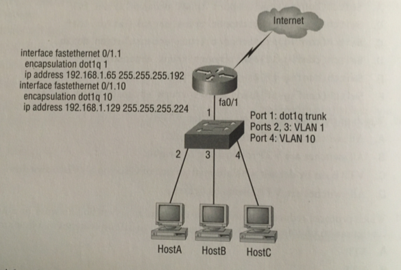
the router port connected tpo the switch is configured using subinterfaces
the switch port connected to the router is a trunk port
the switch ports connected to the hosts are access ports
3. A switch has been configured for three VLANs:
VLAN2
VLAN3
VLAN4
A router has been added to provide communication between the VLANs. What minimum type of
interface is necessary on the router if only one connection is to be made between the router and the switch?
100 Mbps ethernet
you could also use 1Gbps, but 100 Mbps is MINIMUM
4. You want to improve network performance by increasing the bandwidth availbale to hosts and limit
the size of the broadcast domains. Which options will meet goal?
switches with VLANs
5. Protocols that are used to confgure trunking on a switch?
Cisco ISL(deprecated), IEEE 802.1Q
6. When a new trunk link is confiigured on an IOS-based switch, which VLANs are allowed over the link?
all by default, must manually remove to disallow a vlan#
7. Switching technology that reduces the size of broadcast domains?
VLAN
8. VTP mode that allows you to change VLAN information on the switch?
server (not client)
9. Command that will configure a switch port to use the IEEE standard method of inserting VLAN membership information into Ethernet frames?
switchport trunk encapsulation dot1q
switchport mode trunk
NOTE since ISL id deprecated, you should only have type
switchport mode trunk
10. True statement regarding VTP:
all switches are VTP servers by default
11. Protocol that reduces administrative overhead in switched network by allowing the configuration of a new VLAN to be distributed to all the
switches in a domain?
VTP
12. Commands to set a trunk port on a 2960 switch?
switchport mode trunk
13. IEEE standard for frame tagging?
802.1q
14. You connect a host to a switch port, but the new host cannot log into the server that is plugged into the same switch. What could the problem be?
the switchport is on the wrong VLAN
15. Diagram- which three commands can be used to establish a link with the router's FastEthernet interface using the IEEE version of frame tagging?
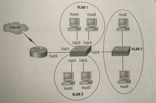
int f0/1
switchport mode trunk
switchport trunk encapsulation dot1q
16. These two switches are not sharing VLAN information. Based on this ouput, what is the reason the switches are not sharing VTP messages?
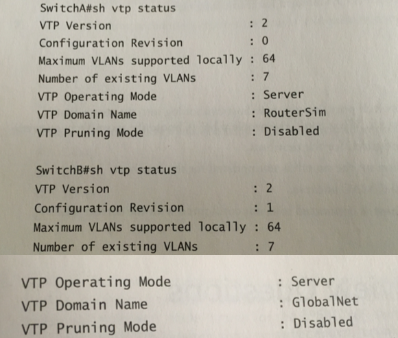
different domain names
17. Which provides multi-VLAN inter-switch communications?
ISL, dot1q
18. Two requirements to configure the VLAN Trunking Protocol to communicate VLAN information between two switches
VTP domain name must match
at least one must be VTP server
19. Three benefits of VLANs
logical groupings of users
enhance network security
increase number of broadcast domains, while reducing the size
20. The four valid modes when a switch port is used as a VLAN trunk?
nongotiate
dynamic desirable
dynamnic auto
trunk (ON)
------------------------------------------------------------
End Chapter 11
10.5 hours 12-31-22 thru 1-2-23
book running total 265.5 hours
book page 606/822
265.5 hours * 60 = 15930 min / 606 pages
26 min/page (includes reading, exercises/labs + online research)
Chapter 12, Security - Notes and Exercises
Rules a packet follows when being compared to an access list:
its always compared with each line of the access list in sequential order
it's compared with lines only until a maches i made. Once a mactch happens, no more comparisons happen.
there is an implicit deny at the end of each list. If the packet matches no lines, it is discarded
Two main types of access list
Standard
Uses only the source IP address in a packet as the condition test. All decisions are made based on the soure IP. Standard access lists permit or deny an entire wsuire ot protocols. They don't distinguis between any of the many types of IP traffic such as Web, Telent, UDP, etc
Extended
Can evaluate many other fiels in the layer 3 and layer 4 headers of a packet. They can eval the source and dest IP, the Protocol field in the Network header,
and the Port number in the Transport header... more granular control
Subtypes..
Named
Named access lists can be either one of the two main types Standard or Extended.
Inbound
inbound packets are processed through access list on the router before being sent to the outbound interface. Denied packets will be discarded..
Outbound
packets are routed to the outbound interface on the router and then processed throgh the lsit before being queued
You can assign one access list:
per interface
per protocol
per direction (one inbound and one outbound per interface)
You cannot remove one line from an access list. If you try, the entire list is removed. Text editor is used for editing lists
Any new entries are added to the bottom
The most specific entries should be at the top

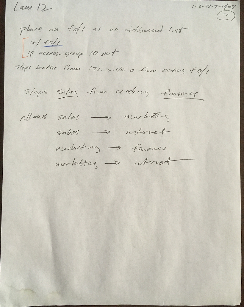
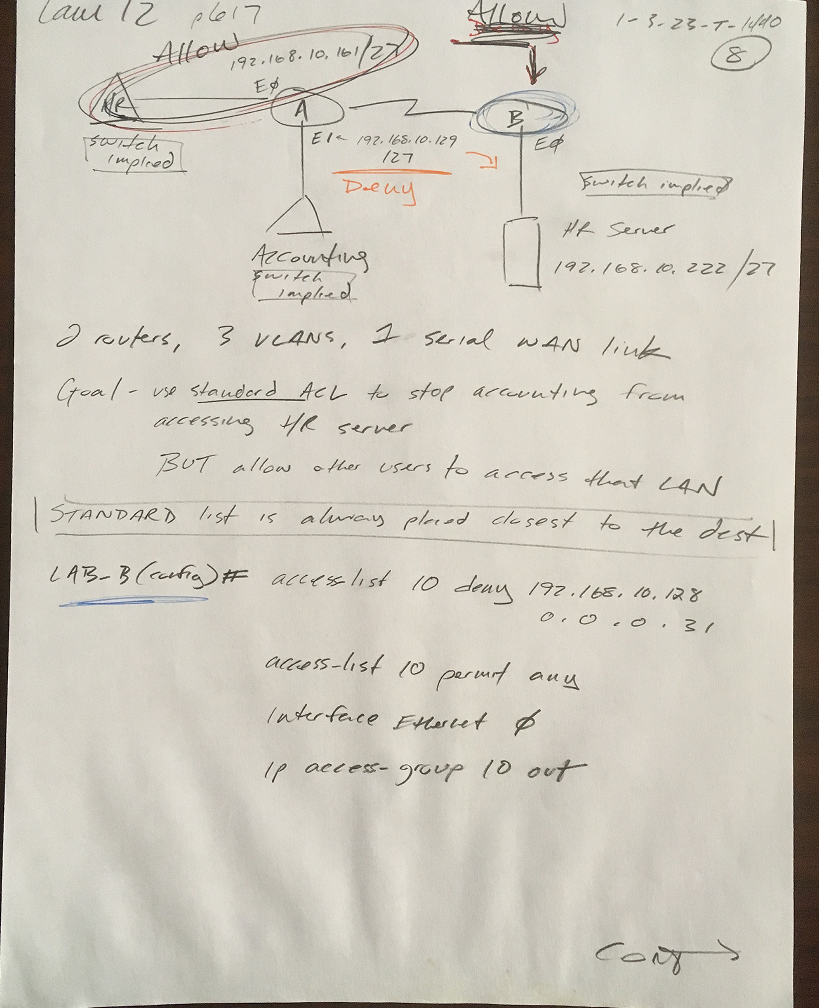
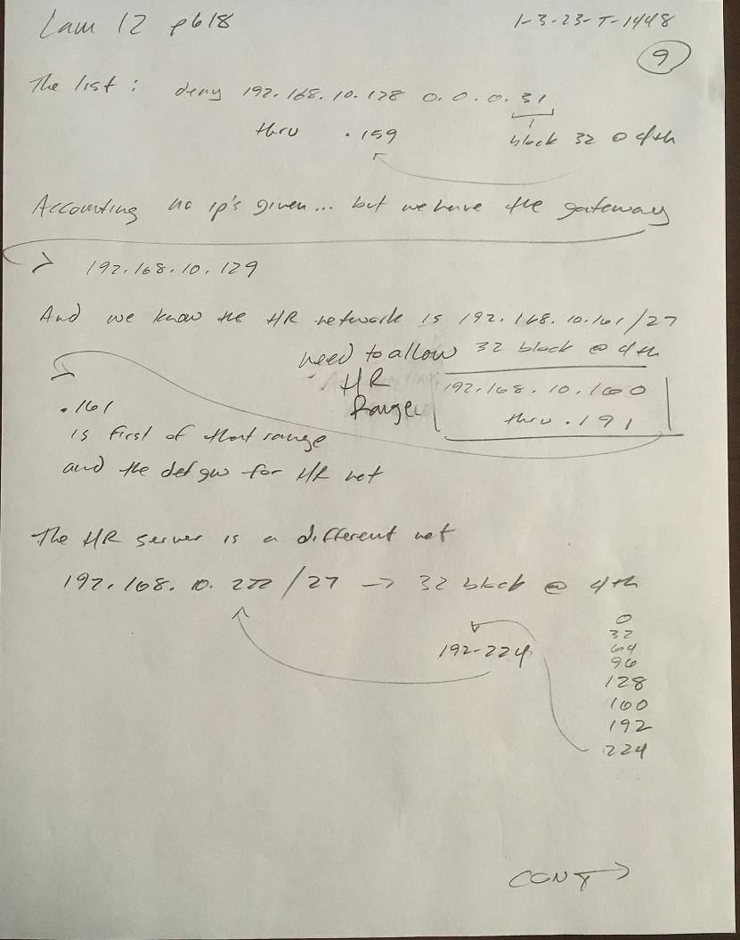


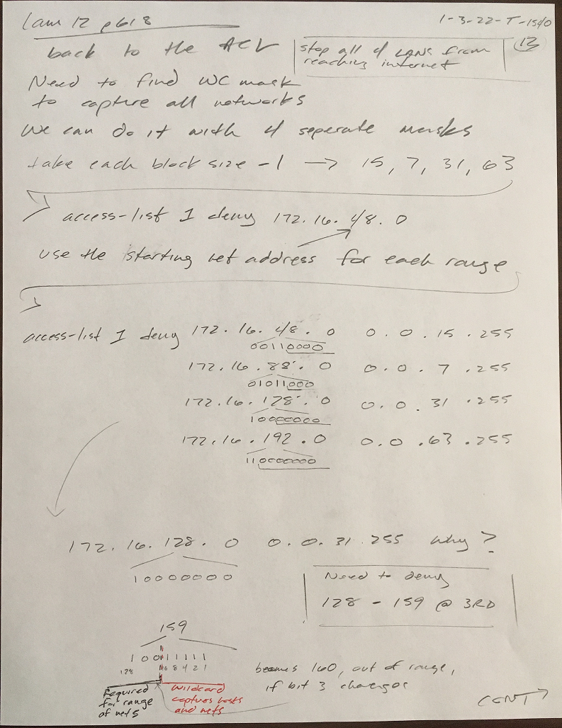

Disabling Services
Block SNMP packets
R(config)#
acces-list 110 deny udp any any eq snmp
R(config)#
int s0/0
R(config-if)#
access-group 110 in
this stops SNMP packets from entering the router (would stop everything else with implicit deny. No permit used in this ex.)
Disable Small Servers
R(config)#
no service tcp-small-servers
R(config)#
no service udp-small-servers
Disable BootP and Auto-Config
R(config)#
no ip boot server
R(config)#
no service config
Disable the HTTP Interface
R(config)#
no ip http server
Disable IP Source Routing
R(config)#
no ip source-route
Disable Proxy ARP
R(config)#
int f0/0
R(config-if)#
no ip proxy-arp
Disable Redirect messages
R(config)#
int f0/0
R(config-if)#
no ip redirects
Disable ICMP Unreachable message
R(config)#
int s0/0
R(config-if)#
no ip unreachables
Disable Multicast Route Caching
R(config)#
int s0/0
R(config-if)#
no ip mroute-cache
Disable MOP- Maintenance Operation Protocol
R(config)#
int s0/0
R(config-if)#
no mop enabled
Disable the X.25 PAD Service
R(config)#
no service pad
Disable Cisco Discovery Protocol
R(config)#
no cdp run
or by interface...
R(config-if)#
no cdp enable
Disable default forwarded UDP protocols
R(config)#
no ip forward-protocol udp 69 TFTP
R(config)#
no ip forward-protocol udp 53 DNS
R(config)#
no ip forward-protocol udp 37 TIME
R(config)#
no ip forward-protocol udp 137 NetBios name resolution
R(config)#
no ip forward-protocol udp 138 NetBios datagram service
R(config)#
no ip forward-protocol udp 68 DHCP
R(config)#
no ip forward-protocol udp 49 TACACS
Recategorize
Disable default forwarded UDP protocols
R(config)#
no ip forward-protocol udp 69 TFTP
R(config)#
no ip forward-protocol udp 53 DNS
R(config)#
no ip forward-protocol udp 37 TIME
R(config)#
no ip forward-protocol udp 137 NetBios name resolution
R(config)#
no ip forward-protocol udp 138 NetBios datagram service
R(config)#
no ip forward-protocol udp 68 DHCP
R(config)#
no ip forward-protocol udp 49 TACACS
Disable BootP
R(config)#
no ip boot server
Disable IP Source Routing
R(config)#
no ip source-route
Disable the HTTP Interface
R(config)#
no ip http server
Disable Redirect messages
R(config)#
int f0/0
R(config-if)#
no ip redirects
Disable ICMP Unreachable message
R(config)#
int s0/0
R(config-if)#
no ip unreachables
Disable Proxy ARP
R(config)#
int f0/0
R(config-if)#
no ip proxy-arp
Disable Multicast Route Caching
R(config)#
int s0/0
R(config-if)#
no ip mroute-cache
Disable Auto-Config
R(config)#
no service config
Disable the X.25 PAD Service
R(config)#
no service pad
Disable Small Servers
R(config)#
no service tcp-small-servers
R(config)#
no service udp-small-servers
Disable MOP- Maintenance Operation Protocol
R(config)#
int s0/0
R(config-if)#
no mop enabled
Cisco's Auto Secure
R#
auto secure
--- AutoSecure Configuration ---
*** AutoSecure configuration enhances the security of
the router, but it will not make it absolutely resistant
to all security attacks ***
AutoSecure will modify the configuration of your device.
All configuration changes will be shown. For a detailed
explanation of how the configuration changes enhance security
and any possible side effects, please refer to Cisco.com for
Autosecure documentation.
At any prompt you may enter '?' for help.
Use ctrl-c to abort this session at any prompt.
Gathering information about the router for AutoSecure
Is this router connected to internet? [no]: yes [enter]
Enter the number of interfaces facing the internet [1]: [enter]
Interface IP-Address OK? Method Status Protocol
GigabitEthernet0/0/0 10.10.1.1 YES manual up down
GigabitEthernet0/0/1 unassigned YES unset administratively down down
GigabitEthernet0/0/2 unassigned YES unset administratively down down
Vlan1 unassigned YES unset administratively down down
Enter the interface name that is facing the internet: gigabitethernet0/0/0
Securing Management plane services...
Disabling service finger
Disabling service pad
Disabling udp & tcp small servers
Enabling service password encryption
Enabling service tcp-keepalives-in
Enabling service tcp-keepalives-out
Disabling the cdp protocol
Disabling the bootp server
Disabling the http server
Disabling the finger service
Disabling source routing
Disabling gratuitous arp
Here is a sample Security Banner to be shown
at every access to device. Modify it to suit your
enterprise requirements.
Authorized Access only
This system is the property of So-&-So-Enterprise.
UNAUTHORIZED ACCESS TO THIS DEVICE IS PROHIBITED.
You must have explicit permission to access this
device. All activities performed on this device
are logged. Any violations of access policy will result
in disciplinary action.
Enter the security banner {Put the banner between
k and k, where k is any character}:# if you are not part of this domain, disconnect now! #
Enable secret is either not configured or
is the same as enable password
Enter the new enable secret: todd
Confirm the enable secret: todd
Enter the new enable password: 1234
Confirm the enable password: 1234
Configuring AAA local authentication
Configuring Console, Aux and VTY lines for
local authentication, exec-timeout, and transport
Securing device against Login Attacks
Configure the following parameters
Blocking Period when Login Attack detected:?
% A decimal number between 1 and 32767.
Blocking Period when Login Attack detected: 100
Maximum Login failures with the device: 5
Maximum time period for crossing the failed login attempts: 10
Configure SSH server? [yes]: [enter]
Enter the host name: lammle.com
Enter the domain-name: lammle.com
Disabling mop on Ethernet interfaces
Securing Forwarding plane services...
Enabling CEF (This might impact the memory requirements for your platform)
Enabling unicast rpf on all interfaces connected
to internet
Configure CBAC Firewall feature? [yes/no]: no
Tcp intercept feature is used prevent tcp syn attack
on the servers in the network. Create autosec_tcp_intercept_list
to form the list of servers to which the tcp traffic is to
be observed
Enable tcp intercept feature? [yes/no]: yes
This is the configuration generated:
!
service password-encryption
no cdp run
access-list 100 permit udp any any eq bootpc
banner motd #go away#
enable secret 5 $1$mERr$V5ujdIM9bTB/I.ipB0gkJ0
enable password 7 08701E1D5D
username todd password 7 0835434A0D
aaa new-model
aaa authentication login local_auth local
line con 0
login authentication local_auth
exec-timeout 5 0
transport output telnet
line vty 0 4
login authentication local_auth
transport input telnet
service timestamps debug datetime msec
service timestamps log datetime msec
logging trap debugging
logging console
logging buffered
line vty 0 4
transport input ssh
transport input telnet
hostname lammle.com
ip domain-name lammle.com
ip access-list extended 100
permit udp any any eq bootpc
Apply this configuration to running-config? [yes]: [enter]
Applying the config generated to running-config
The name for the keys will be: test.test
% The key modulus size is 1024 bits
% Generating 1024 bit RSA keys, keys will be non-exportable...
*Mar 1 22:56:41.001: %SYS-3-CPUHOG: Task is running for (2007)msecs, more than
(2000)msecs (0/0),process = crypto sw pk proc.
-Traceback= 0x824198E0 0x82419FC4 0x8283C238 0x82866AD8 0x828667A8 0x82865D34 0x
828660F4 0x82866510 0x802335D4 0x80236D80 [OK]
lammle.com#
Chapter 12, Security - Exam Essentials
1.Remember the standard and extended IP access-list number ranges
standard 1 - 99
expand standard 1300 - 1999
extended 100-199
expand extended 2000 - 2699
2. Understand the term 'implicit deny'
at the end of every access list is an implicit deny. If a packet does not match any of the lines in the acesss list, it will be discarded.
3. Understand the STANDARD IP access-list configuration commmand
corp(config)#
ip access-list ?
extended Extended Access List
standard Standard Access List
corp(config)#
ip access-list standard?
<1-99> Standard IP access-list number
WORD Access-list name
using a leading "IP" allows you to use a named access list
compare with no "IP" at the front
corp(config)#
access-list ?
<1-99> IP standard access list
<100-199> IP extended access list
4. Understand the EXTENDED IP access-list configuration commmand
corp(config)#
ip access-list extended
<100-199> Extended IP access-list number
WORD name
5. Remember the command to verify an access list on a router interface
corp#
show ip interface
will show if an ACL is set on an interface and which direction it is filtering. Will NOT show the contents of the ACL
6. Remember the command to verify the access-list configuration
corp#
show access-list
will show the content of the lists, but NOT which interfaces have a list set
Chapter 12, Security - Written Lab 12.0
1. What command would you use to configure a standard IP access list to prevent all machines on
network 172.16.0.0/16 from accessing your ethernet network?
corp#
access-list 10 deny 172.16.0.0 0.0.255.255
corp#
access-list 10 permit any
note IP command is optional
2. What command would you use to apply the access list you created in question 1 to an Ethernet interface out?
corp(config)#
int e0/0
corp(config-if)#
ip access-group 10 out
note you MUST use the IP command to apply access-group
3. What command would you use to create an access list that denies host 192.168.15.5 access to an ethernet network?
corp#
access-list 10 deny host 192.168.15.5
corp#
access-list 10 permit any
note subnet mask is NOT needed when using the 'host' switch
4. Which command verifies that you've entered the access list correctly?
corp#
show access-lists
5. Which two tools can help notify and prevent DoS attacks
IDS, IPS
6. What command would you use to create an extended access list that stops host 172.16.10.1 from telnetting to host 172.16.30.5?
corp#
access-list 110 deny tcp host 172.16.10.1 host 172.16.30.5 eq 23
corp#
access-list 110 permit ip any any
7. What command would you use to set the above acces list on a VTY line?
corp#
line vty 0 4
corp(config-line)#
access-class 10 in
8. From question 1, write the same standard IP acess list you used, but this time as a named access list
corp#
ip access-list standard MyACL
corp(config-std-nacl)#
deny 172.16.0.0 0.0.255.255
corp(config-std-nacl)#
permit any
note you MUST use the IP command to create a named list
9. From question 8, write the command to apply the named access list to an eternet interface out
corp#
int e0/0
corp(config-if#
ip access-group MyACL out
note you MUST use the IP command to apply access-group to interface
10. Which command verified the placement and direction of an access list?
corp#
show ip interfaces
but does not show the contents of the ACLs
Chapter 12, Security - Hands-on Labs
Before starting the ACL tasks, we will need to create a topology from scratch based on this diagram. Starting with routers and switches.
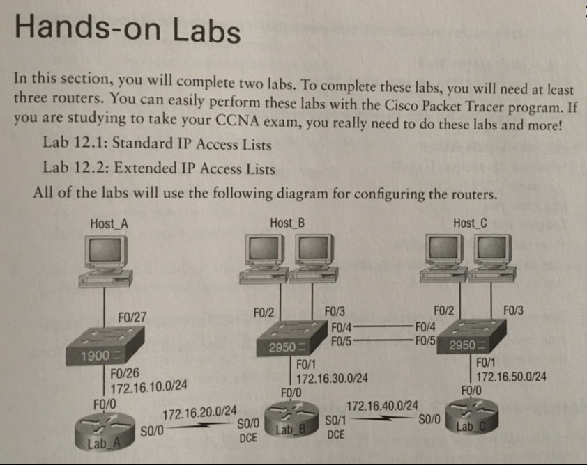

RA(config)#
int f0/0
RA(config-if)#
ip addr 172.16.10.1 255.255.255.0
RA(config-if)#
no shut
RA(config-if)#
int s0/0/0
RA(config-if)#
ip addr 172.16.20.1 255.255.255.0
RA(config-if)#
no shut
SW1(config)#
int vlan 1
SW1(config-if)#
ip addr 172.16.10.2 255.255.255.0
SW1(config-if)#
no shut
RB(config)#
int f0/0
RB(config-if)#
ip addr 172.16.30.1 255.255.255.0
RB(config-if)#
no shut
RB(config-if)#
int s0/0/0
RB(config-if)#
ip addr 172.16.20.2 255.255.255.0
RB(config-if)#
no shut
RB(config-if)#
int s0/0/1
RB(config-if)#
ip addr 172.16.40.1 255.255.255.0
RB(config-if)#
no shut
SW2(config)#
int vlan 1
SW2(config-if)#
ip addr 172.16.30.2 255.255.255.0
SW2(config-if)#
no shut
RC(config)#
int f0/0
RC(config-if)#
ip addr 172.16.50.1 255.255.255.0
RC(config-if)#
no shut
RC(config-if)#
int s0/0/0
RC(config-if)#
ip addr 172.16.40.2 255.255.255.0
RC(config-if)#
no shut
SW3(config)#
int vlan 1
SW3(config-if)#
ip addr 172.16.50.2 255.255.255.0
SW3(config-if)#
no shut
Each router can ping it's neighbor router and switch VLAN address. Need to add hosts and routing protocol. Will try RIP.
RA(config)#
router rip
RA(config-router)#
network 172.16.20.0
RA#
show ip route
Gateway of last resort is not set
172.16.0.0/16 is variably subnetted, 7 subnets, 2 masks
C 172.16.10.0/24 is directly connected, FastEthernet0/0
L 172.16.10.1/32 is directly connected, FastEthernet0/0
C 172.16.20.0/24 is directly connected, Serial0/0/0
L 172.16.20.1/32 is directly connected, Serial0/0/0
R 172.16.30.0/24 [120/1] via 172.16.20.2, 00:00:14, Serial0/0/0
R 172.16.40.0/24 [120/1] via 172.16.20.2, 00:00:14, Serial0/0/0
R 172.16.50.0/24 [120/2] via 172.16.20.2, 00:00:14, Serial0/0/0
RB(config)#
router rip
RB(config-router)#
network 172.16.20.0
RB#
show ip route
Gateway of last resort is not set
172.16.0.0/16 is variably subnetted, 8 subnets, 2 masks
R 172.16.10.0/24 [120/1] via 172.16.20.1, 00:00:15, Serial0/0/0
C 172.16.20.0/24 is directly connected, Serial0/0/0
L 172.16.20.2/32 is directly connected, Serial0/0/0
C 172.16.30.0/24 is directly connected, FastEthernet0/0
L 172.16.30.1/32 is directly connected, FastEthernet0/0
C 172.16.40.0/24 is directly connected, Serial0/0/1
L 172.16.40.1/32 is directly connected, Serial0/0/1
R 172.16.50.0/24 [120/1] via 172.16.40.2, 00:00:24, Serial0/0/1
RC(config)#
router rip
RC(config-router)#
network 172.16.40.0
RC#
show ip route
Gateway of last resort is not set
172.16.0.0/16 is variably subnetted, 7 subnets, 2 masks
R 172.16.10.0/24 [120/2] via 172.16.40.1, 00:00:03, Serial0/0/0
R 172.16.20.0/24 [120/1] via 172.16.40.1, 00:00:03, Serial0/0/0
R 172.16.30.0/24 [120/1] via 172.16.40.1, 00:00:03, Serial0/0/0
C 172.16.40.0/24 is directly connected, Serial0/0/0
L 172.16.40.2/32 is directly connected, Serial0/0/0
C 172.16.50.0/24 is directly connected, FastEthernet0/0
L 172.16.50.1/32 is directly connected, FastEthernet0/0
All PC's can ping eachother
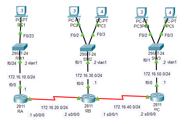
Chapter 12, Security - Hands-on Lab 12.1 Standard IP Access Lists
Need to alllow only packets from Host B to enter network 172.16.10.0
RA(config)#
access-list 10 permit 172.16.30.3 0.0.0.0
RA(config)#
int f0/0
RA(config-if)#
ip access-group 10 out
Now only PC2 can ping though RA to PC1. Every other IP is now blocked by implicit deny.
Since this is a standard ACL it should be placed closet to the target (network 172.16.16.0). So we place the ACL on RA's outbound interface to that network.
PC2#
ping 172.16.10.3
Pinging 172.16.10.3 with 32 bytes of data:
Request timed out.
Reply from 172.16.10.3: bytes=32 time=1ms TTL=126
Reply from 172.16.10.3: bytes=32 time=1ms TTL=126
Reply from 172.16.10.3: bytes=32 time=9ms TTL=126
Ping statistics for 172.16.10.3:
Packets: Sent = 4, Received = 3, Lost = 1 (25% loss),
Approximate round trip times in milli-seconds:
Minimum = 1ms, Maximum = 9ms, Average = 3ms
try pinging PC1 from another host
PC5#
ping 172.16.10.3
Pinging 172.16.10.3 with 32 bytes of data:
Reply from 172.16.20.1: Destination host unreachable.
Reply from 172.16.20.1: Destination host unreachable.
Reply from 172.16.20.1: Destination host unreachable.
Reply from 172.16.20.1: Destination host unreachable.s
alternative command formats
RA(config)#
access-list 10 permit host 172.16.30.3
When using the HOST switch, you do not need a mask
remove the ACL to prepare for next lab
RA(config)#
int f0/0
RA(config-if)#
no ip access-group 10 out
RA(config)#
ip access-list standard ListA
RA(config-std-nacl)#
permit 172.16.30.0 0.0.0.255
when not using the HOST switch, you can specify a single host OR a range by using the wildcard mask.
ACL number is not required
Chapter 12, Security - Hands-on Lab 12.2 Extended IP Access Lists
Need to stop PC1 at 172.16.10.3 from creating a Telnet session to RB at 172.16.20.2 but still allow PC1 to ping RB.
RA(config)#
access-list 110 deny tcp host 172.16.10.3 host 172.16.20.2 eq telnet
RA(config)#
access-list 110 permit ip any 0.0.0.0 255.255.255.255
RA(config)#
int f0/0
RA(config-if)#
ip access-group 110 in
Note extended ACL is placed closest to the source (PC1 at 172.16.10.3) which is RA int f0/0 inbound
The telnet traffic from PC1 intended for RB will not make it out of RA
Enable Telnet on the router
RB(config)#
line vty 0 15
RB(config-line)#
password todd
RB(config-line)#
login
Try Telnet from PC1 to RB
PC1#
telnet 172.16.20.2
Trying 172.16.20.2 ...
% Connection timed out; remote host not responding
Try Telnet from PC2 to RB
PC2#
telnet 172.16.20.2
User Access Verification
Password:
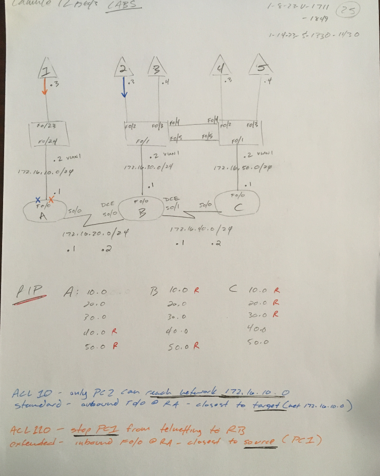
Chapter 12, Security - Review
1. which is an example of a standard IP access list?
access-list 1 deny 172.16.10.1 0.0.0.0
Note you must use a WILDCARD MASK with ACLs
2. You need to create an access list that will prevent hosts in the network range of 192.168.160.0 to 192.168.191.0. Which list to use?
access-list 1 deny 192.168.160.0 0.0.31.255
WC octet is one less than the block size
3. You have created a named access list called Blocksales. Which is a valid command for applying this to packets trying to enter interfaces s0 of your router.
ip access-group Blocksales in
dont forget the leading "ip"
4. Which are 2 valid ways to refer to only host 172.16.30.55 in an IP access list?
172.16.30.55 0.0.0.0
host 172.16.30.55
5. Which access list will only allow HTTP traffic into network 196.15.7.0
acccess-list 110 permit tcp any 196.15.7.0 0.0.0.255 eq www
110 specified extended. Permit TCP something.. Anybody inbound. Restricted to this /24 network. The traffic being permitted must be HTTP
6. What router command allows you to determine wheter an IP acces list is enabled on a particular interface?
show ip interface
[cut]
Outgoing access list is not set
Inbound access list is 110
[cut]
can also use show run
7. Which router command allows you to view the entire contents of all access lists?
show access-lists
shows the rules of each list, but NOT which interfaces are included
8. IF you wanted to deny all Telent connections to only network 192.168.10.0, which command could you use?
access-list 100 deny tcp any 192.168.10.0 0.0.0.255 eq 23
9. If you want to deny FTP access from network 200.200.10.0 to network 100.199.11.0, but allow everything else, which command is valid?
access-list 198 deny tcp 200.200.10.0 0.0.0.255 100.199.11.0 0.0.0.255 eq ftp
access-list 198 permit ip any 0.0.0.0 255.255.255.255
any source (word format), any dest (address format)
10. You want to create a standard access list that denies the subnet of host 192.16.50.172/20. Which would you start your list with?
access-list 10 deny 172.16.48.0 0.0.15.255
16 block at 3rd
11. Which command to apply to an access list to a router interface?
ip access-group 101 in
will not work without the leading "ip"
12. You want to create a standard access list that denies the subnet of host 172.16.198.94/19 Which would you start your list with?
access-list 10 deny 172.16.192.0 0.0.31.255
32 block at 3rd
13. You want to create a standard access list that denies the subnet of host 172.16.144.17/21 Which would you start your list with?
access-list 10 deny 172.16.144.0 0.0.7.255
8 block at 3rd
14. Which command connects access list 110 inbound to interface ethernet0?
(after selecting the interface, indicated by config-if prompt)
RA(config-if)#
ip access-group 110 in
15. What command will permit SMTP mail to only host 1.1.1.1?
access-list 110 permit TCP any host 1.1.1.1 eq SMTP
not saying "any host"..
rather, "any" source to the destination "host 1.1.1.1"
no mask needed for 1.1.1.1. since we used the host param
16. What will the result of this access list be:
access-list 110 deny tcp 10.1.1.128 0.0.0.63 any eq smtp
access-list 110 deny tcp any any eq 23
int ethernet 0
ip access-group 110 out
no traffic will be allowed out ethernet0. Our two explicit statemnts block smtp and telnet.
But since we have no 'permit' statement at the end, the implicit deny blocks everything, in addition to our two rules.
17. Which series of commands will restrict Telnet access to the router?
RA(config)#
access-list 10 permit 172.16.1.1
RA(config)#
line vty 0 4
RA(config-line)#
access-class 10 in
restricts everyone but the listed IP
no leading "IP" needed for access-class
WC mask is optional..? dont need to use 'host' param? System will know if it is a host or network?
I was confused by this answer because I thought the mask was required if not using the host param.. Did some testing with RouterC in this topology in packet tracer to better understand the syntax.
Ex.1 Standard ACL
RC(config)#
access-list 10 ?
deny Specify packets to reject
permit Specify packets to forward
remark Access list entry comment
RC(config)#
access-list 10 permit ?
A.B.C.D Address to match
any Any source host
host A single host address
RC(config)#
access-list 10 permit 172.16.1.1 ENTER (random example address)
RC(config)#
do show access-list
Standard IP access list 10
10 permit host 172.16.1.1
Even though I did not use the HOST param.. the ACL processed the given address as a host
Ex.2 Standard ACL
What if we try omitting the HOST param, but giving a NETWORK address..
RC(config)#
access-list 10 permit 172.16.50.0 ENTER
RC(config)#
do show access-list
Standard IP access list 10
10 permit host 172.16.1.1
20 permit host 172.16.50.0
Again the rule automatically applied the HOST param. I am surprised the system didnt recoginze 50.0 as a network address...
Ex. 3 Extended ACL
SW1(config)#
access-list 110 permit tcp 172.16.50.1 172.16.50.2 eq 23 ENTER
% Incomplete command.
^ Here I tried to give a source and dest IP without the HOST param or supplying mask info. The command errored.
SW1(config)#
access-list 110 permit tcp ?
A.B.C.D Source address
any Any source host
host A single source host
Again let's try giving a network address with the HOST param
SW1(config)#
access-list 110 permit tcp host 172.16.50.0 host 172.16.50.2 eq 23 ENTER
SW1(config)#
do show access-list ENTER
Standard IP access list 10
10 permit host 172.16.1.1
20 permit host 172.16.50.0
Extended IP access list 110
10 permit tcp host 172.16.50.0 host 172.16.50.2 eq telnet
Again it works.. would this cause problems later? The ACL shows 50.0 as a host, with no mask info provided.
Takeaways
When using a STANDARD ACL.. you do not have to use the HOST param. But if you omit it and fail to supply a mask, the given address will be classified as a host ID; even if it is actually a network ID.
The EXTENDED ACL behaves differently- you are required to either use the HOST param, which allows ommission of mask info.
Or if you dont use the HOST param you must supply mask info to complete the command.
For both STANDARD and EXTENDED, if you use the HOST param.. the system will not error if you supply a network id... The address will appear as a "host" in the ACL
18. True statement regarding access lists applied to an interface?
one list per direction, per layer 3 protocol, per interface
19. What is the most common attack on a network today?
DOS Denial of Service
20. You need to stop DoS attacks in real time and have a log of anyone who has tried to attack your network. Whad whould you do?
Implement IDS/IPS
------------------------------------------------------------
End Chapter 12
16 hours 1-2 thru 1-14-2023
book running total 281.5 hours
book page 654/822
281.5 * 60 = 16890 min / 654 pages
26 min/page (includes reading, exercises/labs + online research)
Chapter 13, NAT - Exercises
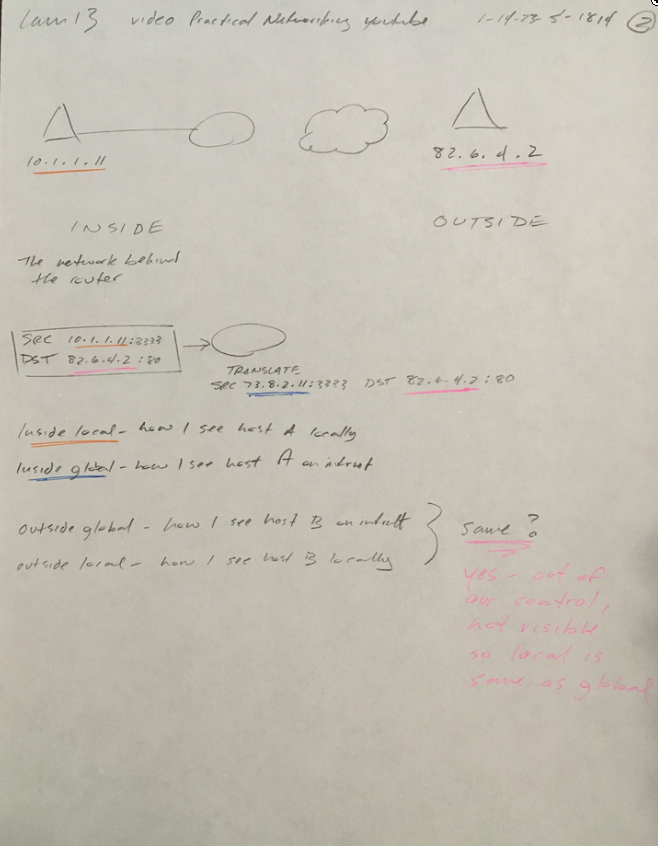

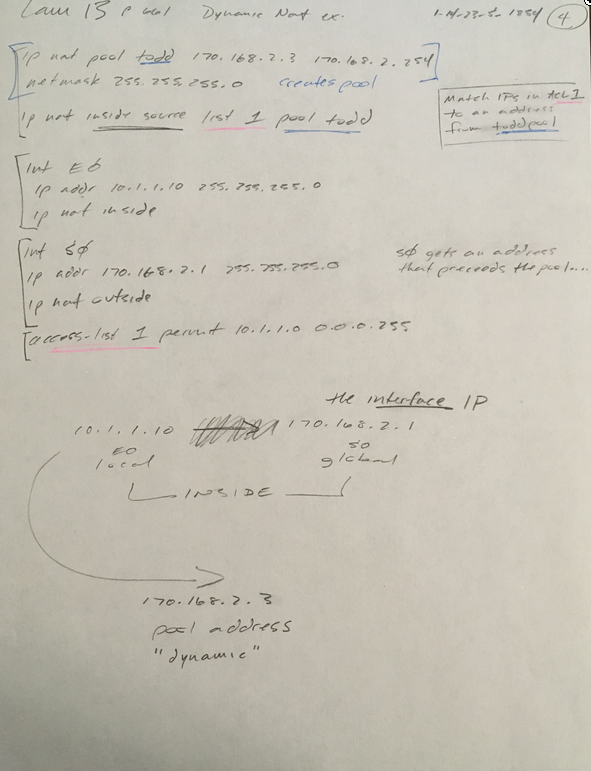
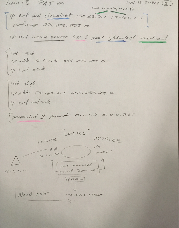
Chapter 13, NAT - Exam Essentials
1. Understand the term NAT
AKA 'masquerading', 'IP-masquerading', 'Network Address Translation', all referrring to the process of rewriting the source/destination addresses
of IP packets when they traverse a router or firewall.
2. Remember the three methods of NAT
STATIC - one to one
DYNAMIC - one to one(from a pool)
OVERLOADED- one to many(using ports)
3. Understand static NAT
one inside local gets statically assigned to one inside global
4. Understand dyanamic NAT
range of inside locals can dynamically map to range of inside globals
5. Understand overloading
range of inside locals with port number added map to single inside global
Chapter 13, NAT - Written Lab 13.0
1. What type of address translation can use only one address to allow thousands of hosts to be translated globally?
PAT
2. What command can you use to show the NAT translations as the occour on your router?
dubg ip nat
3. What command will show you the translation table?
show ip nat translations
4. What command will clear all your NAT entries from the translation table?
clear ip nat translations *
5. An inside local is before or after translation?
before
6. An inside global is before or after translation?
after
7. Which command can be used for troubleshooting and displays a summary of the NAT configuration as well as counts of active translation types and hits to an eisting mapping?
show ip nat statistics
8. What commands must be used on your router interfaces before NAT will translate addresses?
ip nat inside
and
ip nat outside
9. In this output what type of NAT is being used?
ip nat pool todd-nat 170.168.10.10 170.168.10.20 netmask 255.255.255.0
dynamic
10. Instead of the netmask command you can use the ___________ statement.
prefix-length
Chapter 13, NAT - Hands-on Lab 13.1 Preparing for NAT
Disable timeout for all 4 routers
Router(config)#
line con 0
Router(config-line)#
exec-timeout 0
Set interface addresses
C(config)#
int f0/0
C(config-if)#
ip addr 192.168.30.2 255.255.255.0
C(config-if)#
no shut
B(config)#
int f0/0
B(config-if)#
ip addr 192.168.30.1 255.255.255.0
B(config-if)#
no shut
B(config-if)#
int s0/0/0
B(config-if)#
ip addr 192.168.20.2 255.255.255.0
B(config-if)#
no shut
A(config)#
int s0/0/0
A(config-if)#
ip addr 192.168.20.1 255.255.255.0
A(config-if)#
no shut
A(config-if)#
int s0/0/1
A(config-if)#
ip addr 171.16.10.2 255.255.255.0
A(config-if)#
no shut
ISP(config)#
int s0/0/0
ISP(config-if)#
ip addr 171.16.10.1 255.255.255.0
ISP(config-if)#
no shut
Configure RIP, set a passive interface and configure the default network.
A(config)#
router rip
A(config-router)#
network 192.168.20.0
A(config-router)#
network 171.16.10.0
A(config-router)#
passive-interface s0/0/1
Stops RIP updates from being sent to the ISP.
A(config-router)#
exit
A(config)#
ip default-network 171.16.10.1
A#
show ip route
Gateway of last resort is not set
171.16.0.0/16 is variably subnetted, 3 subnets, 3 masks
S 171.16.0.0/16 [1/0] via 171.16.10.1
C 171.16.10.0/24 is directly connected, Serial0/0/1
L 171.16.10.2/32 is directly connected, Serial0/0/1
192.168.20.0/24 is variably subnetted, 2 subnets, 2 masks
C 192.168.20.0/24 is directly connected, Serial0/0/0
L 192.168.20.1/32 is directly connected, Serial0/0/0
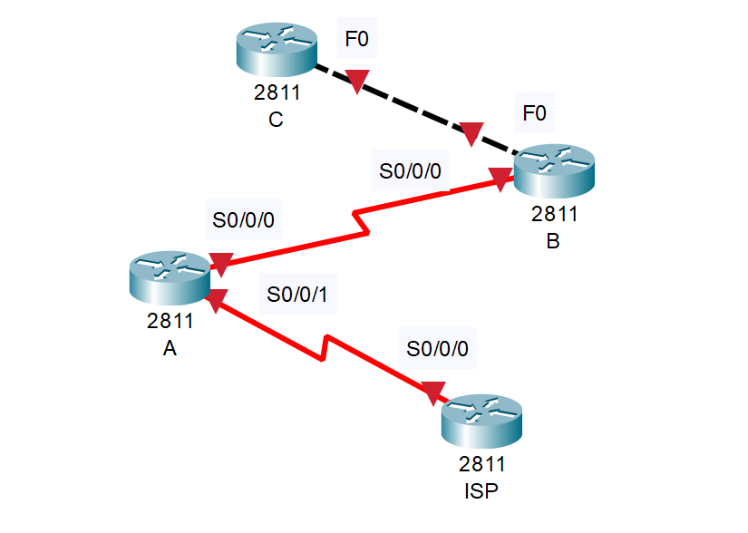
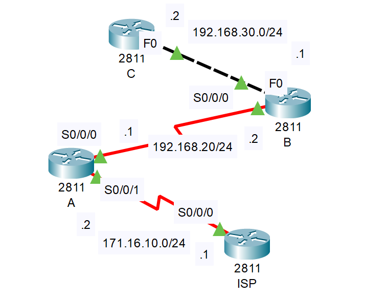
B(config)#
router rip
B(config-router)#
network 192.168.30.0
B(config-router)#
network 192.168.20.0
B#
show ip route
Gateway of last resort is not set
192.168.20.0/24 is variably subnetted, 2 subnets, 2 masks
C 192.168.20.0/24 is directly connected, Serial0/0/0
L 192.168.20.2/32 is directly connected, Serial0/0/0
192.168.30.0/24 is variably subnetted, 2 subnets, 2 masks
C 192.168.30.0/24 is directly connected, FastEthernet0/0
L 192.168.30.1/32 is directly connected, FastEthernet0/0
C(config)#
router rip
C(config-router)#
network 192.168.30.0
C#
show ip route
Gateway of last resort is not set
R 192.168.20.0/24 [120/1] via 192.168.30.1, 00:00:10, FastEthernet0/0
192.168.30.0/24 is variably subnetted, 2 subnets, 2 masks
C 192.168.30.0/24 is directly connected, FastEthernet0/0
L 192.168.30.2/32 is directly connected, FastEthernet0/0
PROBLEM
RIP is not working correctly. RA is not seeing the 30.0 net and RB is not seeing the 10.0 net.
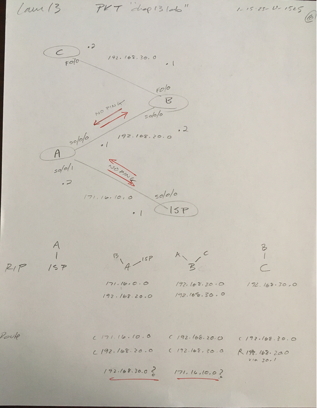
This thread suggests trying the RIP command "no auto-summary", which I did. But the issue didnt resolve. Since the book didnt say to use "no auto-summary", I didn't think that was the problem.
But the thread gave me two ideas: to try pinging between the routers, which I had not yet done. And that maybe the Serial connections had an issue. The only RIP route working correctly was for RouterC,
which had no serial connection...


Before disconnecting the cable, I looked at the connection overview, which seemed fine:
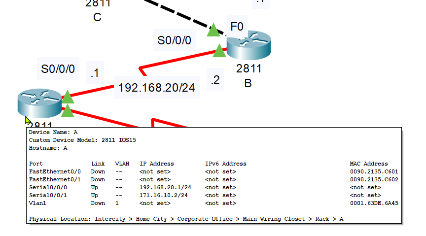
But after disconnecting the cable between RA and ISP and then trying to reconnect, I identified the issue.
RA s0/0/0 is actually facing east. I have that interface set for the 192 network. But in the diagram it appears it's on the 171 network.


This isnt obvious when looking at the connection overview.. it says that s0/0/0 is set for the 192 network, which is true. The problem is I thuoght that port was facing north.
RIP is not working bc these routers are not connected; RA's interfaces have the wrong IP's, so ISP and RB cant communicate.
Checking the ip int brief for the routers is also not helpful. This mistake highlights the importance of plugging he right cables into the right ports and having accurate diagrams.
But we can get some useful info with show cdp neighbor
NOTE I also discovered a typo on the ISP interface
A#
show ip int br
Interface IP-Address OK? Method Status Protocol
FastEthernet0/0 unassigned YES unset administratively down down
FastEthernet0/1 unassigned YES unset administratively down down
Serial0/0/0 192.168.20.1 YES manual up up
Serial0/0/1 171.16.10.2 YES manual up up
Vlan1 unassigned YES unset administratively down down
A#
show cdp neighbor
Capability Codes: R - Router, T - Trans Bridge, B - Source Route Bridge
S - Switch, H - Host, I - IGMP, r - Repeater, P - Phone
Device ID Local Intrfce Holdtme Capability Platform Port ID
B Ser 0/0/1 153 R C2800 Ser 0/0/0
ISP Ser 0/0/0 168 R C2800 Ser 0/0/0
ISP#
show ip int br
Interface IP-Address OK? Method Status Protocol
FastEthernet0/0 unassigned YES unset administratively down down
FastEthernet0/1 unassigned YES unset administratively down down
Serial0/0/0 172.16.10.1 YES manual up up
Serial0/0/1 unassigned YES unset administratively down down
Vlan1 unassigned YES unset administratively down down
ISP#
show cdp neighbor
Capability Codes: R - Router, T - Trans Bridge, B - Source Route Bridge
S - Switch, H - Host, I - IGMP, r - Repeater, P - Phone
Device ID Local Intrfce Holdtme Capability Platform Port ID
A Ser 0/0/0 164 R C2800 Ser 0/0/0
Comparing this output with the topology diagram reveals the issue. ISP is finding RA at RA s0/0/0 but that int is on the 192 network. Layer 2 connectivity is fine, but IP addresses are wrong.
to fix, I will trade the ip addresses for s0/0/0 and s0/0/1 on RA. And correct the labels on the diagram
A(config)#
int s0/0/0
A(config-if)#
no ip addr
A(config-if)#
int s0/0/1
A(config-if)#
no ip addr
A(config-if)#
ip addr 171.16.10.0 255.255.255.0
A(config-if)#
int s0/0/0
A(config-if)#
ip addr 192.168.20.0 255.255.255.0
A#
show ip int br
Interface IP-Address OK? Method Status Protocol
FastEthernet0/0 unassigned YES unset administratively down down
FastEthernet0/1 unassigned YES unset administratively down down
Serial0/0/0 171.16.10.2 YES manual up up
Serial0/0/1 192.168.20.1 YES manual up up
Vlan1 unassigned YES unset administratively down down

Now let's check the routing tables again
A#
show ip route
Gateway of last resort is not set
171.16.0.0/16 is variably subnetted, 3 subnets, 3 masks
S 171.16.0.0/16 [1/0] via 171.16.10.1
C 171.16.10.0/24 is directly connected, Serial0/0/0
L 171.16.10.2/32 is directly connected, Serial0/0/0
192.168.20.0/24 is variably subnetted, 2 subnets, 2 masks
C 192.168.20.0/24 is directly connected, Serial0/0/1
L 192.168.20.1/32 is directly connected, Serial0/0/1
R 192.168.30.0/24 [120/1] via 192.168.20.2, 00:00:08, Serial0/0/1
B#
show ip route
Gateway of last resort is not set
192.168.20.0/24 is variably subnetted, 2 subnets, 2 masks
C 192.168.20.0/24 is directly connected, Serial0/0/0
L 192.168.20.2/32 is directly connected, Serial0/0/0
192.168.30.0/24 is variably subnetted, 2 subnets, 2 masks
C 192.168.30.0/24 is directly connected, FastEthernet0/0
L 192.168.30.1/32 is directly connected, FastEthernet0/0
C#
show ip route
Gateway of last resort is not set
R 192.168.20.0/24 [120/1] via 192.168.30.1, 00:00:08, FastEthernet0/0
192.168.30.0/24 is variably subnetted, 2 subnets, 2 masks
C 192.168.30.0/24 is directly connected, FastEthernet0/0
L 192.168.30.2/32 is directly connected, FastEthernet0/0
(no RIP set on ISP)
ISP#
show ip route
Gateway of last resort is not set
171.16.0.0/16 is variably subnetted, 2 subnets, 2 masks
C 171.16.10.0/24 is directly connected, Serial0/0/0
L 171.16.10.1/32 is directly connected, Serial0/0/0
I solved the problem of having no route for 192.168.30.0 on RA.
But we should see a route for 171.16.10.0 on C
Again here are the RIP configs
A(config-router)#
network 192.168.20.0
A(config-router)#
network 171.16.0.0
B(config-router)#
network 192.168.30.0
B(config-router)#
network 192.168.20.0
C(config-router)#
network 192.168.30.0
B advertises 30 to A
B advertises 20 to C
but A is not advertising 10 to anyone. And why do we need C to advertise 30, if B already advertises 30?
Moving on in hopes this will become clearer
ISP Configs
ISP(config)#
ip route 0.0.0.0 0.0.0.0 s0
default route to the corporate networks
ISP(config)#
line vty 0 4
ISP(config)#
no login
suppresses password prompt
Chapter 13, NAT - Hands-on Lab 13.2 Configuring Dynamic NAT
A Configs
1. create pool
A(config)#
ip nat pool GlobalNet 171.16.10.50 171.16.10.55 net 255.255.255.255.0
2. create ACL
A(config)#
access-list 1 permit 192.168.20.0 0.0.0.255
A(config)#
access-list 1 permit 192.168.30.0 0.0.0.255
3. map ACL to pool
A(config)#
ip nat inside source list 1 pool GLobalNet
4. configure interfaces
A(config#
int s0/0/1
A(config-int)#
ip nat inside
A(config-int)#
int s0/0/0
A(config-int)#
ip nat outside
C Configs
C#
telnet 171.16.10.1
Telnet fails, and now it is clear why B could not receive the 171 network via A. Going back to having the interfaces reversed...
Per the A configs we set s0/0/1 as passive interface. I thought that interface faced the ISP router. It actually faced router B.
Rip updates were not moving from A to B. They could move to ISP, but since RIP is not set on ISP, it did not process them.
after setting s/0/0/0 as passive on A, here is all the CORRECT routing toplogy..
A#
show ip route
Gateway of last resort is not set
171.16.0.0/16 is variably subnetted, 3 subnets, 3 masks
S 171.16.0.0/16 [1/0] via 171.16.10.1
C 171.16.10.0/24 is directly connected, Serial0/0/0
L 171.16.10.2/32 is directly connected, Serial0/0/0
192.168.20.0/24 is variably subnetted, 2 subnets, 2 masks
C 192.168.20.0/24 is directly connected, Serial0/0/1
L 192.168.20.1/32 is directly connected, Serial0/0/1
R 192.168.30.0/24 [120/1] via 192.168.20.2, 00:00:10, Serial0/0/1
B#
show ip route
Gateway of last resort is not set
R 171.16.0.0/16 [120/1] via 192.168.20.1, 00:00:18, Serial0/0/0
192.168.20.0/24 is variably subnetted, 2 subnets, 2 masks
C 192.168.20.0/24 is directly connected, Serial0/0/0
L 192.168.20.2/32 is directly connected, Serial0/0/0
192.168.30.0/24 is variably subnetted, 2 subnets, 2 masks
C 192.168.30.0/24 is directly connected, FastEthernet0/0
L 192.168.30.1/32 is directly connected, FastEthernet0/0
C#
show ip route
Gateway of last resort is not set
R 171.16.0.0/16 [120/2] via 192.168.30.1, 00:00:07, FastEthernet0/0
R 192.168.20.0/24 [120/1] via 192.168.30.1, 00:00:07, FastEthernet0/0
192.168.30.0/24 is variably subnetted, 2 subnets, 2 masks
C 192.168.30.0/24 is directly connected, FastEthernet0/0
L 192.168.30.2/32 is directly connected, FastEthernet0/0
(no RIP set on ISP)
ISP#
show ip route
Gateway of last resort is 0.0.0.0 to network 0.0.0.0
171.16.0.0/16 is variably subnetted, 2 subnets, 2 masks
C 171.16.10.0/24 is directly connected, Serial0/0/0
L 171.16.10.1/32 is directly connected, Serial0/0/0
S* 0.0.0.0/0 is directly connected, Serial0/0/0
Try C Configs again
C#
telnet 171.16.10.1
Trying 171.16.10.1 ...Open
ISP>
B Configs
B#
telnet 171.16.10.1
Trying 171.16.10.1 ...Open
ISP>
show user
Line User Host(s) Idle Location
0 con 0 idle 00:03:00
324 vty 0 idle 00:00:06 171.16.10.50
*325 vty 1 idle 00:00:00 171.16.10.51
Success-
A at 171.16.10.2 is mapped to 171.16.10.50
B at 192.168.20.2 is mapped to 171.16.10.51
Note this is one to one, limited to the amount of addresses in the pool
ctrl+shift+6, release, X
B#
telnet 192.168.20.1
A>
show ip nat translations
Pro Inside global Inside local Outside local Outside global
tcp 171.16.10.50:1025 192.168.30.2:1025 171.16.10.1:23 171.16.10.1:23
tcp 171.16.10.50:1026 192.168.30.2:1026 171.16.10.1:23 171.16.10.1:23
tcp 171.16.10.50:1027 192.168.30.2:1027 171.16.10.1:23 171.16.10.1:23
tcp 171.16.10.51:1025 192.168.20.2:1025 171.16.10.1:23 171.16.10.1:23
This does not look like the results from the book- why are ports being used? I did not specify 'overload'
I got pretty bogged down here since the book gives this output in the example:
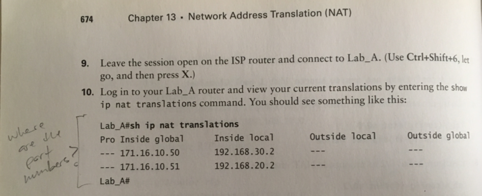
I recreated the entire lab with 1941 routers instead of 2811's, and got the same result when running
show ip nat translations
Not until I removed my dynamic NAT pool, and set STATIC NAT, did I output like illustrated in the book, with no port numbers.
After extensive research, the only conclusion I can draw is that at the time of publishing(2011), IOS worked differenty.
All the sources I checked show the port numbers as normal with Dynamic NAT (NO PAT) configured. For example, these two videos.
This thread also seems to confirm....

Chapter 13, NAT - Hands-on Lab 13.3 Configuring PAT
1. Delete translation table and remove the dynamic NAT Pool
A#
clear ip nat translation *
A(config)#
no ip nat pool GlobalNet 171.16.10.50 171.16.10.55 netmask 255.255.255.0
%Pool GlobalNet in use, cannot destroy
need to unlink the ACL first...
A(config)#
no ip nat inside source list 1 pool GlobalNet
A(config)#
no ip nat pool GlobalNet 171.16.10.50 171.16.10.55 netmask 255.255.255.0
2. Create new pool(with only one address) and ACL
A(config)#
ip nat pool LAMMLE 171.16.10.100 171.16.10.100 net 255.255.255.0
A(config)#
access-list 2 permit 192.168.20.0 0.0.0.255
A(config)#
access-list 2 permit 192.168.30.0 0.0.0.255
3. Map ACL to the pool, allow PAT by using 'overload'
A(config)#
ip nat inside source list 2 pool LAMMLE overload
output
3. Telnet from both B and C to ISP. The sessions traverse A. Check the status on A.
B#
telnet 171.16.10.1
Trying 171.16.10.1 ...Open
ISP>
C#
telnet 171.16.10.1
Trying 171.16.10.1 ...Open
ISP>
4. Check the statuses on ISP and A.
ISP#
show users
Line User Host(s) Idle Location
* 0 con 0 idle 00:00:00
324 vty 0 idle 00:01:44 171.16.10.100
325 vty 1 idle 00:01:42 171.16.10.100
A#
show ip nat translations
Pro Inside global Inside local Outside local Outside global
tcp 171.16.10.100:1026 192.168.30.2:1026 171.16.10.1:23 171.16.10.1:23
tcp 171.16.10.100:1027 192.168.20.2:1027 171.16.10.1:23 171.16.10.1:23
Takeaway:
We see port numbers, just as before with Dynamic NAT. But this time, both inside local IPs are being translated to THE SAME inside global IP
Send one ping command from C @ 192.168.30.2
to ISP @ 171.16.10.1
and from Lab A we can see the translations
C#
ping 171.16.10.1
A#
debut ip nat
NAT: s=192.168.30.2->171.16.10.100, d=171.16.10.1 [24]
NAT*: s=171.16.10.1, d=171.16.10.100->192.168.30.2 [105]
NAT: s=192.168.30.2->171.16.10.100, d=171.16.10.1 [25]
NAT*: s=171.16.10.1, d=171.16.10.100->192.168.30.2 [106]
NAT: s=192.168.30.2->171.16.10.100, d=171.16.10.1 [26]
NAT*: s=171.16.10.1, d=171.16.10.100->192.168.30.2 [107]
NAT: s=192.168.30.2->171.16.10.100, d=171.16.10.1 [27]
NAT*: s=171.16.10.1, d=171.16.10.100->192.168.30.2 [108]
NAT: s=192.168.30.2->171.16.10.100, d=171.16.10.1 [28]
NAT*: s=171.16.10.1, d=171.16.10.100->192.168.30.2 [109]
Chapter 13, NAT - Review
1.Three disadvantages of NAT?
lost of end-to-end IP traceability
certain applications will not function with NAT
translation introduces switching path delays
2. Three advantages of NAT?
conserves legally registered addresses
increases flexibility when connecting to the internet
remedies address overlap occurence
3. Which command will allow to to see real-timne translations on router?
debug ip nat
4. Which command will show you all the active translations on router?
show ip nat translations
5. Which command will clear all translations from router?
clear ip nat translations
6. Which command to see the summary of the NAT configuration?
show ip nat statistics
7. Command to crete a dynamic pool named Todd what will provide you with 30 global addresses?
ip nat pool Todd 171.16.10.65 171.16.10.94 net 255.255.255.224
Note pool name is case-sensitive
8. What are three methods of NAT?
static, dynamic, overloaded
9. When creating a pool of global addresses, what can be used instead of the netmask command?
prefix-length
10. What is a good starting point for troubleshooting if your router is not translatig?
check interfaces for correct configs
11. 3 good reasons to run NAT?
you need to merge two intranets with duplicatte ip addresses
you need to connect to the internet but hosts dont have unique addresses
you change to a new ISP that requires you to renumber your network
12. What is the name for inside hosts address after translation?
inside global
13. What is the name for inside hosts address before translation?
inside local
14. Based on this output, which command would allow dynamic translations?
Pro Inside global Inside local Outside local Outside global
--- 1.1.128.1 10.1.1.1 --- ---
--- 1.1.130.178 10.1.1.2 --- ---
--- 1.1.129.174 10.1.1.10 --- ---
--- 1.1.130.101 10.1.1.89 --- ---
--- 1.1.134.169 10.1.1.100 --- ---
--- 1.1.135.174 10.1.1.200 --- ---
Need to cover 128 thru 135 in the 3rd octet for inside global addresses. Block size 8 will do it.
ip nat pool todd 1.1.128.1 1.1.135.254 prefix-length 21
128.1 thru 135.254 is the range of usabel addresses for network 1.1.128.0
we start with 128.1 since it is the first address specified in the question. The use 8 block to capture 135.174
to get 8 block, use /21
15. Your inside locals are not being translated to the inside global addreses. Which commands will show if your inside globals are allowed to use the NAT pool?
ip nat pool Corp 198.18.41.129 198.18.41.134 netmask 255.255.255.248
ip nat inside source list 100 int pool Corp overload
show access-list
we need to find out if access-list 100 includes any address
16. What command would you place on the interface of a private network?
ip nat inside
17. Command to place on an interface connected to the Internet?
ip nat outside
18. Pat Address Translation is also called what?
NAT overload
19. What does the astersik represent in this output:
NAT*: s=172.16.2.2, d=192.168.2.1->10.1.1.1 [1]
The packet was translated and fast-switched to the destination
Fast switching creates a route cache in order to quickly forward packets through a router without having the parse the routing table for every packet.
As packets are looked up in the routing table, the info is cached for later use
20. What is the missing piece of this config to enable PAT?
ip nat pool Corp 198.18.41.129 198.18.41.134 netmask 255.255.255.248 access-list 1 permit 192.168.76.64 0.0.0.31
ip nat inside source list 1 pool Corp overload
----------------------------------------------------------
End Chapter 13
16.5 hours 1-14 thru 1-16-2023
book running total 298 hours
book page 683/822
298 hours * 60 = 17880 min / 683 pages
26 min/page (includes reading, exercises/labs + online research)
Chapter 14, Wireless - Exam Essentials
1. Understand the IEEE 802.11a specification
ans
2. Understand the IEEE 802.11b specification
ans
3. Understand the IEEE 802.11g specification
ans
4. Understand the IEEE 802.11n specification
ans
5. Understand WVoIP requirements
ans
Chapter 14, Wireless - Written Lab 14.0
1. What is the max data rate of 802.11b?
ans
2. What is the max data rate of 802.11g?
ans
3. T/F - the TKIP encryption is based on RC4
ans
4. What is the frequence range of 802.11b?
ans
5. What is the frequence range of 802.11g?
ans
6. What is the frequence range of 802.11a?
ans
7. Which feature of 802.11n provides MAC efficiency?
ans
8. WPA2 uses which encryption method?
ans
9. Which IEEE committee has been sanctioned by WPA and is called WPA2?
ans
10. What device must be on your wired network when running an enterprise EAP solution?
ans
Chapter 14, Wireless - Review
1. Three EAP types that allow wireless LANs in enterprise networks?
ans
2. What is the freq range of 802.11b?
ans
3. What is the freq range of 802.11a?
ans
4. What is the freq range of 802.11g?
ans
5. You have finished physically installing an access point on the ceiling of your office. At a minimum, which parameter must be configured on the access point
in order to allow a wireless client to operate on it?
ans
6. Which encryption type does WPA2 use?
ans
7. How many non-overlapping channels are available with 802.11b?
ans
8. A single 802.11g access point has been configure and installed in the center of a square-shaped office. A few wireless users are experiencing slow performance
and drops while most users are operating at peak efficiency. What are three likely causes of the problem?
ans
9. What is the max data rate for 802.11a?
ans
10. What is the max data rate for 802.11g?
ans
11. What is the max data rate for 802.11b?
ans
12. Two practices that help secure the configuration utilities on WAPs from unatuthorized access?
ans
13. A wireless client cannot connect to an 802.11b/g BSS with a b/g wireless card. The client section of the access point does not list any active WLAN clients.
What is the possible issue?
ans
14. Which two features did WPA add to address the inherent weaknesses found in WEP?
ans
15. Which two wireless encryption methods are based on RC4?
ans
16. Two workers have established wireless communications directly between their wireless laptops. What type of wireless topology is this?
ans
17. Two descriptions of the wireless security standard that WPA defines?
ans
18. Which wireless LAN desgin ensures that a moble wireless client will not lose connectivity when moving between WAPs?
ans
19. You are connecting your access point and it is set to root. What does the extended service set ID mean?
ans
20. What are three basic parameters to configure on a WAP?
ans
Chapter 15, IPv6 - Exam Essentials
Chapter 15, IPv6 - Written Lab 15.0
Chapter 15, IPv6 - Review
Chapter 16, WANs - Exam Essentials
Chapter 16, WANs - Written Lab 16.0
Chapter 16, WANs - Hands-on Lab 16.1 Configuring PPP Encapsulation and Authentication
Chapter 16, WANs - Hands-on Lab 16.2 Configuring and Monitoring HDLC
Chapter 16, WANs - Hands-on Lab 16.3 Configuring Frame Relay and Subinterfaces
Chapter 16, WANs - Review
WORKSHEET TEMPLATE
CHAPTER / SECTION TITLE
1.
ans
2.
ans
3.
ans
4.
ans
5.
ans
6.
ans
7.
ans
8.
ans
9.
ans
10.
ans
11.
ans
12.
ans
13.
ans
14.
ans
15.
ans
16.
ans
17.
ans
18.
ans
19.
ans
20.
ans
Reference
PROBLEM
SW1#
command
output
Core#
command
output
SW2#
command
output
SW1(config)#
command
output
Prompt#
command
output
Switch 1 setup - 2960, 24-port (book version of this model is 8-port)
SW1(config)# enable secret todd
SW1(config)# int f0/1
SW1(config-if)# description 1st connection to core switch
SW1(config-if)# int f0/2
SW1(config-if)# desc 2nd connection to core switch
SW1(config-if)# int f0/3
SW1(config-if)# desc connection to HostA
SW1(config-if)# int f0/4
SW1(config-if)# desc connection to PhoneA
SW1(config-if)# int f0/8
SW1(config-if)# desc connection to IVR
SW1(config-if)# line console 0
SW1(config-line)# password console
SW1(config-line)# login
SW1(config-line)# exit
SW1(config)# line vty ?
SW1(config-line)# password telnet
SW1(config-line)# login
SW1(config-line)# int vlan 1
SW1(config-if)# ip addr 192.168.10.17 255.255.255.240
SW1(config-if)# no shut
SW1(config)# banner motd # MOTD: This is the SW1 switch #
SW1(config)# exit
SW1(config)# enable secret todd
SW1(config)# int f0/1
SW1(config-if)# description 1st connection to core switch
SW1(config-if)# int f0/2
SW1(config-if)# desc 2nd connection to core switch
SW1(config-if)# int f0/3
SW1(config-if)# desc connection to HostA
SW1(config-if)# int f0/4
SW1(config-if)# desc connection to PhoneA
SW1(config-if)# int f0/8
SW1(config-if)# desc connection to IVR
SW1(config-if)# line console 0
SW1(config-line)# password console
SW1(config-line)# login
SW1(config-line)# exit
SW1(config)# line vty ?
<0-15> First Line number
SW1(config)#
line vty 0 15
SW1(config-line)# password telnet
SW1(config-line)# login
SW1(config-line)# int vlan 1
SW1(config-if)# ip addr 192.168.10.17 255.255.255.240
SW1(config-if)# no shut
%LINK-5-CHANGED: Interface Vlan1, changed state to up
SW1(config-if)#
exit
SW1(config)# banner motd # MOTD: This is the SW1 switch #
SW1(config)# exit
%SYS-5-CONFIG_I: Configured from console by console
SW1#
copy run start
Destination filename [startup-config]?
ENTER
Building configuration...
[OK]
Switch 2 setup - 3560, 24-port (book version of this model is 8-port)
SW2(config)# enable secret todd
SW2(config)# int f0/1
SW2(config-if)# description 1st connection to core switch
SW2(config-if)# int f0/2
SW2(config-if)# desc 2nd connection to core switch
SW2(config-if)# int f0/3
SW2(config-if)# desc connection to HostB
SW2(config-if)# int f0/4
SW2(config-if)# desc connection to PhoneB
SW2(config-if)# line console 0
SW2(config-line)# password console
SW2(config-line)# login
SW2(config-line)# exit
SW2(config)# line vty ?
SW2(config-line)# password telnet
SW2(config-line)# login
SW2(config-line)# int vlan 1
SW2(config-if)# ip addr 192.168.10.18 255.255.255.240
S1 SW2(config-if)# no shut
SW2(config)# banner motd # MOTD: This is the SW2 switch #
SW2(config)# exit
SW2(config)# enable secret todd
SW2(config)# int f0/1
SW2(config-if)# description 1st connection to core switch
SW2(config-if)# int f0/2
SW2(config-if)# desc 2nd connection to core switch
SW2(config-if)# int f0/3
SW2(config-if)# desc connection to HostB
SW2(config-if)# int f0/4
SW2(config-if)# desc connection to PhoneB
SW2(config-if)# line console 0
SW2(config-line)# password console
SW2(config-line)# login
SW2(config-line)# exit
SW2(config)# line vty ?
<0-15> First Line number
SW2(config)#
line vty 0 15
SW2(config-line)# password telnet
SW2(config-line)# login
SW2(config-line)# int vlan 1
SW2(config-if)# ip addr 192.168.10.18 255.255.255.240
S1 SW2(config-if)# no shut
%LINK-5-CHANGED: Interface Vlan1, changed state to up
SW2(config-if)#
exit
SW2(config)# banner motd # MOTD: This is the SW2 switch #
SW2(config)# exit
%SYS-5-CONFIG_I: Configured from console by console
SW2#
copy run start
Destination filename [startup-config]?
ENTER
Building configuration...
[OK]
Core Switch setup - 3550 Multilayer (sub for book version 3650)
Core(config)# enable secret todd
Core(config)# int g1/0/1
Core(config-if)# desc 1st connection to SW2
Core(config-if)# int g1/0/2
Core(config-if)# desc 2nd connection to SW2
Core(config-if)# int g1/0/3
Core(config-if)# desc 1st connection to SW1
Core(config-if)# int g1/0/4
Core(config-if)# desc 2nd connection to SW1
Core(config-if)# line con 0
Core(config-line)# password console
Core(config-line)# line vty 0 15
Core(config-line)# password telnet
Core(config-line)# login
Core(config-line)# int vlan 1
Core(config-if)# ip addr 192.168.10.19 255.255.255.240
Core(config-if)# no shut
Core(config-if)# exit
Core(config)# banner motd # This is the core switch #
Core(config)# exit
Core# copy run start
Core(config)# enable secret todd
Core(config)# int g1/0/1
Core(config-if)# desc 1st connection to SW2
Core(config-if)# int g1/0/2
Core(config-if)# desc 2nd connection to SW2
Core(config-if)# int g1/0/3
Core(config-if)# desc 1st connection to SW1
Core(config-if)# int g1/0/4
Core(config-if)# desc 2nd connection to SW1
Core(config-if)# line con 0
Core(config-line)# password console
Core(config-line)# line vty 0 15
Core(config-line)# password telnet
Core(config-line)# login
Core(config-line)# int vlan 1
Core(config-if)# ip addr 192.168.10.19 255.255.255.240
Core(config-if)# no shut
Core(config-if)# exit
Core(config)# banner motd # This is the core switch #
Core(config)# exit
Core# copy run start
Destination filename [startup-config]?
ENTER
Building configuration...
[OK]
Prompt#
command
output
I got stuck while setting up these switches. I will go through my thought process in finding the solution to the problem. (Documenting this in HTML is very time consuming, but I think it is worthwhile)
Lets stop and take a look at exactly what the book is laying out for us:
As noted, I am having to substitue different models. Packet Tracer 8.2 has these options:
Todd mentions that the 2960 and 3560 are 8-port models. Packet Tracer doesnt offer any 8-port models.
I tried to match the models as closely as possible.
2950 already matches (but not 8-port)
3650 sub for 3550
3560 already matches (but not 8-port)
I anticipated mismatched port numbers between the book's switches and packet tracer's, so I planned to make substitutions:
| Device | Book Port | PKT Port | |
|---|---|---|---|
| SW1 | f0/1 | f0/1 | 1st conn to Core |
| SW1 | f0/2 | f0/2 | 2nd conn to Core |
| SW1 | f0/3 | f0/3 | to HostA |
| SW1 | f0/4 | f0/4 | to PhoneA |
| SW1 | f0/8 | f0/8 | to IVR |
| ------------------------------------------- | |||
| SW2 | fa0/1 | f0/1 | 1st conn to Core |
| SW2 | fa0/2 | f0/2 | 2nd conn to Core |
| SW2 | fa0/3 | f0/3 | to HostB |
| SW2 | fa0/4 | f0/4 | to PhoneB |
I havent had to change anything up to this point... but note that I programmed each interface using "f" instead of using "fa".
The book uses "f" and "fa", seemingly interchangeably.... I'll discuss this more in a moment...
Core switch:
| Device | Book Port | PKT Port | |
|---|---|---|---|
| Core | f0/5 | g1/0/1 | 1st conn to SW2 |
| Core | fa0/5 | g1/0/2 | 2nd conn to SW2 |
| Core | fa0/7 | g1/0/3 | 1st conn to SW1 |
| Core | fa0/8 | g1/0/4 | 2nd conn to SW1 |
This got tricky because the interface labels are completely different.
I started to wonder.....
If I had been able to find a switch that used the same port names, and attempted to configure exactly as shown in the book, wouldn't fa0/5 have overwritten f0/5... assuming the "A" is optional and each command is interchangeable?
After some research, I am satisfied that there is actually no difference between 'F' and 'FA'.
Reference
And I started thinking, could this be a typo in the book. So I referred back to the Wiley site, where I have already identified one typo that had me confused, earlier in the book.
Sure enough, this is a mistake:
Still doesnt quite explain why he was using exclusively "FA" on SwitchA, then "F" on SwitchB and Core. Maybe to prove a point, that they are interchangeable. I couldn't find anything that suggests it matters which is used.
Interestingly:
I discovered a new command through this investigation. Since show ip int brief gives you the full interface name, but doesnt show the "official" abbreviated versions.
Interface IP-Address OK? Method Status Protocol
GigabitEthernet1/0/1 unassigned YES unset down down
GigabitEthernet1/0/2 unassigned YES unset down down
GigabitEthernet1/0/3 unassigned YES unset down down
GigabitEthernet1/0/4 unassigned YES unset down down
I found that show int status shows the ABBREVIATIONS used on the device. I checked on several devices, and this helped convince me that there is "no such thing" as an "F" interface vs an "FA" interface.. other than being a shorthand equivalent.
To access the the 4 interfaces below, we could use "Gig", "Gi" or just "G"
Port Name Status Vlan Duplex Speed Type
Gig1/0/1 1st conn to SW2 notconnect 1 auto auto 10/100BaseTX
Gig1/0/2 2nd conn to SW2 notconnect 1 auto auto 10/100BaseTX
Gig1/0/3 1st connection to notconnect 1 auto auto 10/100BaseTX
Gig1/0/4 2nd connection to notconnect 1 auto auto 10/100BaseTX/span>
SW1#
show interface status
Port Name Status Vlan Duplex Speed Type
Fa0/1 1st connection to connected 1 auto auto 10/100BaseTX
Fa0/2 2nd connection to connected 1 auto auto 10/100BaseTX
Fa0/3 connection to Host connected 1 auto auto 10/100BaseTX
Fa0/4 connection to Phon connected 1 auto auto 10/100BaseTX
Fa0/5 notconnect 1 auto auto 10/100BaseTX
Fa0/6 notconnect 1 auto auto 10/100BaseTX
Fa0/7 notconnect 1 auto auto 10/100BaseTX
Fa0/8 connection to IVR notconnect 1 auto auto 10/100BaseTX
Core#
show interface status
Gig1/0/1 1st conn to SW2 connected 1 auto auto 10/100BaseTX
Gig1/0/2 2nd conn to SW2 connected 1 auto auto 10/100BaseTX
Gig1/0/3 1st connection to connected 1 auto auto 10/100BaseTX
Gig1/0/4 2nd connection to connected 1 auto auto 10/100BaseTX
SW2#
show interface status
Fa0/1 1st connection to connected 1 auto auto 10/100BaseTX
Fa0/2 2nd connection to connected 1 auto auto 10/100BaseTX
Fa0/3 connection to Host connected 1 auto auto 10/100BaseTX
Fa0/4 connection to Phon connected 1 auto auto 10/100BaseTX
IVR#
show interface status
output
Ping from S2 to S1, going through Corp
SW2# ping 192.168.10.17
SW2# ping 192.168.10.17
Sending 5, 100-byte ICMP Echos to 192.168.10.17, timeout is 2 seconds:
..!!!
Success rate is 60 percent (3/5), round-trip min/avg/max = 0/0/1 ms
REPEAT Ping from S2 to S1, going through Corp
SW2# ping 192.168.10.17
SW2# ping 192.168.10.17
Sending 5, 100-byte ICMP Echos to 192.168.10.17, timeout is 2 seconds:
!!!!!
Success rate is 100 percent (5/5), round-trip min/avg/max = 0/0/2 ms
From Core, Ping SW1
Core# ping 192.168.10.17
Core# ping 192.168.10.17
Sending 5, 100-byte ICMP Echos to 192.168.10.17, timeout is 2 seconds:
..!!!
Success rate is 60 percent (3/5), round-trip min/avg/max = 0/0/0 ms
From Core, Ping SW2
Core# ping 192.168.10.17
Core# ping 192.168.10.17
Sending 5, 100-byte ICMP Echos to 192.168.10.18, timeout is 2 seconds:
.!!!!
Success rate is 80 percent (4/5), round-trip min/avg/max = 0/0/0 ms
REPEAT From Core, Ping SW1
Core# ping 192.168.10.17
Core# ping 192.168.10.17
Sending 5, 100-byte ICMP Echos to 192.168.10.17, timeout is 2 seconds:
!!!!!
Success rate is 100 percent (5/5), round-trip min/avg/max = 0/0/2 ms
REPEAT From Core, Ping SW2
Core# ping 192.168.10.17
Core# ping 192.168.10.17
Sending 5, 100-byte ICMP Echos to 192.168.10.18, timeout is 2 seconds:
!!!!!
Success rate is 100 percent (5/5), round-trip min/avg/max = 0/0/1 ms
SW1(config)# int range f0/3 - 4
SW1(config-if-range)# switchport mode access
Default port mode is "desirable"-- meaning they will trunk if they are connected to another switch. You cannot set port security on a port in desirable mode, so we set the port to Access mode
SW1(config-if-range)# switchport port-security enables security
SW1(config-if-range)# switchport port-security maximum ?
<1-132> Maximum addresses
SW1(config-if-range)# switchport port-security maximum 1
max of 1 mac allowed
SW1(config-if-range)# switchport port-security mac-address sticky
only the first MAC will be allowed to send frames
SW1(config-if-range)# switchport port-security violation ?
<1-132> protect Security violation protect mode
restrict Security violation restrict mode
shutdown Security violation shutdown mode
SW1(config-if-range)# switchport port-security violation shutdown
if a second MAC connects, the port will be shut down
SW1# show port-security
<1-132>
Secure Port MaxSecureAddr CurrentAddr SecurityViolation Security Action
(Count) (Count) (Count)
--------------------------------------------------------------------
Fa0/3 1 0 0 Shutdown
Fa0/4 1 0 0 Shutdown
----------------------------------------------------------------------
SW1# show port-security interface f0/3
<1-132>
% Invalid input detected at '^' marker.
SW1#show port-security interface f0/3
Port Security : Enabled
Port Status : Secure-up
Violation Mode : Shutdown
Aging Time : 0 mins
Aging Type : Absolute
SecureStatic Address Aging : Disabled
Maximum MAC Addresses : 1
Total MAC Addresses : 0
Configured MAC Addresses : 0
Sticky MAC Addresses : 0
Last Source Address:Vlan : 0000.0000.0000:0
Security Violation Count : 0
Two alternative violation modes to shutdown:
Protect- another host can connect, but frames will be dropped
Restrict- alerts via SNMP that a violation has occurred on the port
SW1#(config)
int range f0/3 - 4
SW1#(config-if-range) spanning-tree portfast ?
SW1#(config-if-range) spanning-tree bpduguard enable
The next few commands from book are N/A in Packet Tracer
SW1#(config-if) spanning-tree ?
SW1#(config) spanning-tree uplinkfast N/A
SW1#(config) do show spanning-tree uplinkfast N/A
SW1#(config) do show spanning-tree mode rapid-pvst N/A
SW1#(config-if-range) spanning-tree portfast ?
disable Disable portfast for this interface
trunk Enable portfast on the interface even in trunk mode
SW1#(config-if-range)
spanning-tree portfast
%Warning: portfast should only be enabled on ports connected to a single
host. Connecting hubs, concentrators, switches, bridges, etc... to this
interface when portfast is enabled, can cause temporary bridging loops.
Use with CAUTION
%Portfast has been configured on FastEthernet0/3 but will only
have effect when the interface is in a non-trunking mode.
%Warning: portfast should only be enabled on ports connected to a single
host. Connecting hubs, concentrators, switches, bridges, etc... to this
interface when portfast is enabled, can cause temporary bridging loops.
Use with CAUTION
%Portfast has been configured on FastEthernet0/4 but will only
have effect when the interface is in a non-trunking mode.
SW1#(config-if-range) spanning-tree bpduguard enable
The next few commands from book are N/A in Packet Tracer
SW1#(config-if) spanning-tree ?
bpduguard Don't accept BPDUs on this interface
cost Change an interface's spanning tree port path cost
guard Change an interface's spanning tree guard mode
link-type Specify a link type for spanning tree protocol use
portfast Enable an interface to move directly to forwarding on link up
vlan VLAN Switch Spanning Tree
SW1#(config) spanning-tree uplinkfast N/A
SW1#(config) do show spanning-tree uplinkfast N/A
SW1#(config) do show spanning-tree mode rapid-pvst N/A
SW2#(config)
int range f0/3 - 4
SW2#(config-if-range) spanning-tree portfast ?
SW2#(config-if-range) spanning-tree bpduguard enable
The next few commands from book are N/A in Packet Tracer
SW2#(config-if) spanning-tree ?
SW2#(config) spanning-tree uplinkfast N/A
SW2#(config) do show spanning-tree uplinkfast N/A
SW2#(config) do show spanning-tree mode rapid-pvst N/A
SW2#(config-if-range) spanning-tree portfast ?
disable Disable portfast for this interface
trunk Enable portfast on the interface even in trunk mode
SW2#(config-if-range)
spanning-tree portfast
%Warning: portfast should only be enabled on ports connected to a single
host. Connecting hubs, concentrators, switches, bridges, etc... to this
interface when portfast is enabled, can cause temporary bridging loops.
Use with CAUTION
%Portfast has been configured on FastEthernet0/3 but will only
have effect when the interface is in a non-trunking mode.
%Warning: portfast should only be enabled on ports connected to a single
host. Connecting hubs, concentrators, switches, bridges, etc... to this
interface when portfast is enabled, can cause temporary bridging loops.
Use with CAUTION
%Portfast has been configured on FastEthernet0/4 but will only
have effect when the interface is in a non-trunking mode.
SW2#(config-if-range) spanning-tree bpduguard enable
The next few commands from book are N/A in Packet Tracer
SW2#(config-if) spanning-tree ?
bpduguard Don't accept BPDUs on this interface
cost Change an interface's spanning tree port path cost
guard Change an interface's spanning tree guard mode
link-type Specify a link type for spanning tree protocol use
portfast Enable an interface to move directly to forwarding on link up
vlan VLAN Switch Spanning Tree
SW2#(config) spanning-tree uplinkfast N/A
SW2#(config) do show spanning-tree uplinkfast N/A
SW2#(config) do show spanning-tree mode rapid-pvst N/A
SW1# show spanning-tree
VLAN0001
Spanning tree enabled protocol ieee
Root ID Priority 32769
Address 0001.645B.5321
Cost 38
Port 1(FastEthernet0/1)
Hello Time 2 sec Max Age 20 sec Forward Delay 15 sec
Bridge ID Priority 32769 (priority 32768 sys-id-ext 1)
Address 00E0.F7BC.472E
Hello Time 2 sec Max Age 20 sec Forward Delay 15 sec
Aging Time 20
Interface Role Sts Cost Prio.Nbr Type
---------------- ---- --- --------- -------- --------------------------------
Fa0/1 Root FWD 19 128.1 P2p
Fa0/2 Altn BLK 19 128.2 P2p
Fa0/3 Desg FWD 19 128.3 P2p
Fa0/4 Desg FWD 19 128.4 P2p
SW2# show spanning-tree
VLAN0001
Spanning tree enabled protocol ieee
Root ID Priority 32769
Address 0001.645B.5321
This bridge is the root
Hello Time 2 sec Max Age 20 sec Forward Delay 15 sec
Bridge ID Priority 32769 (priority 32768 sys-id-ext 1)
Address 0001.645B.5321
Hello Time 2 sec Max Age 20 sec Forward Delay 15 sec
Aging Time 20
Interface Role Sts Cost Prio.Nbr Type
---------------- ---- --- --------- -------- --------------------------------
Fa0/1 Desg FWD 19 128.1 P2p
Fa0/3 Desg FWD 19 128.3 P2p
Fa0/2 Desg FWD 19 128.2 P2p
Fa0/4 Desg FWD 19 128.4 P2p
Core# show spanning-tree
VLAN0001
Spanning tree enabled protocol ieee
Root ID Priority 32769
Address 0001.645B.5321
Cost 19
Port 1(GigabitEthernet1/0/1)
Hello Time 2 sec Max Age 20 sec Forward Delay 15 sec
Bridge ID Priority 32769 (priority 32768 sys-id-ext 1)
Address 0001.96B3.31BC
Hello Time 2 sec Max Age 20 sec Forward Delay 15 sec
Aging Time 20
Interface Role Sts Cost Prio.Nbr Type
---------------- ---- --- --------- -------- --------------------------------
Gi1/0/1 Root FWD 19 128.1 P2p
Gi1/0/2 Altn BLK 19 128.2 P2p
Gi1/0/4 Desg FWD 19 128.4 P2p
Gi1/0/3 Desg FWD 19 128.3 P2p
SW1(config)# int port-channel 1
SW1(config-if)# int range f0/1-2
SW1(config-if-range)# switchport mode trunk
SW1(config-if-range)# switchport nonegotiate
SW1(config-if-range)# channel-group 1 mode desirable
%LINEPROTO-5-UPDOWN: Line protocol on Interface
FastEthernet0/1, changed state to down
%LINEPROTO-5-UPDOWN: Line protocol on Interface
FastEthernet0/1, changed state to up
%LINEPROTO-5-UPDOWN: Line protocol on Interface
FastEthernet0/2, changed state to down
%LINEPROTO-5-UPDOWN: Line protocol on Interface
FastEthernet0/2, changed state to up
SW1# show interface etherchannel
----
FastEthernet0/1:
Port state = 1
Channel group = 1 Mode = Desirable-S1 Gcchange = 0
Port-channel = Po1 GC = 0x00000000 Pseudo port-channel = Po1
Port index = 0 Load = 0x00 Protocol = PAgP
Flags: S - Device is sending Slow hello. C - Device is in Consistent state.
A - Device is in Auto mode. P - Device learns on physical port.
d - PAgP is down.
Timers: H - Hello timer is running. Q - Quit timer is running.
S - Switching timer is running. I - Interface timer is running.
Local information:
Hello Partner PAgP Learning Group
Port Flags State Timers Interval Count Priority Method Ifindex
Fa0/1 d U1/S1 H30s 1 0 128 Any 0
Age of the port in the current state: 00d:00h:00m:00s
----
FastEthernet0/2:
Port state = 1
Channel group = 1 Mode = Desirable-S1 Gcchange = 0
Port-channel = Po1 GC = 0x00000000 Pseudo port-channel = Po1
Port index = 0 Load = 0x00 Protocol = PAgP
Flags: S - Device is sending Slow hello. C - Device is in Consistent state.
A - Device is in Auto mode. P - Device learns on physical port.
d - PAgP is down.
Timers: H - Hello timer is running. Q - Quit timer is running.
S - Switching timer is running. I - Interface timer is running.
Local information:
Hello Partner PAgP Learning Group
Port Flags State Timers Interval Count Priority Method Ifindex
Fa0/2 d U1/S1 H30s 1 0 128 Any 0
Age of the port in the current state: 00d:00h:00m:00s
----
Port-channel1:Port-channel1
Age of the Port-channel = 00d:00h:27m:57s
Logical slot/port = 2/1 Number of ports = 0
GC = 0x00000000 HotStandBy port = null
Port state =
Protocol = 2
Port Security = Disabled
Core(config)# int port-channel 1
Core(config-if)# int range g1/0/3-4
Core(config-if-range)# switchport encap dot1q
% Interface range command failed for GigabitEthernet1/0/3
% Command failed on interface GigabitEthernet1/0/3. Aborting
The interfaces are failing to join the etherchannel..
alternate path:
Core(config)# int range g1/0/3-4
Core(config-if-range)# channel-group 1 mode on
%LINK-5-CHANGED: Interface Port-channel1, changed state to up
%LINEPROTO-5-UPDOWN: Line protocol on Interface Port-channel1, changed state to up
%PM-4-ERR_DISABLE: channel-misconfig error detected on Gig1/0/3, putting Gig1/0/3 in err-disable state
%LINK-3-UPDOWN: Interface GigabitEthernet1/0/3, changed state to down
%LINEPROTO-5-UPDOWN: Line protocol on Interface GigabitEthernet1/0/3, changed state to down
%LINEPROTO-5-UPDOWN: Line protocol on Interface Port-channel1, changed state to down
Core# show etherchannel summary
Flags: D - down P - in port-channel
I - stand-alone s - suspended
H - Hot-standby (LACP only)
R - Layer3 S - Layer2
U - in use f - failed to allocate aggregator
u - unsuitable for bundling
w - waiting to be aggregated
d - default port
Number of channel-groups in use: 1
Number of aggregators: 1
Group Port-channel Protocol Ports
------+-------------+-----------+----------------------------------------------
1 Po1(SD) - Gig1/0/3(D) Gig1/0/4(D)
Core(config)# int port-channel 1
Core(config-if)# switchport mode trunk
Core(config-if)# int port-channel 1
Core(config-if)# exit
Core(config)# int range g1/0/3-4
Core(config-if-range)# channel-group 1 mode desirable
Lammle 2011
int port-channel 1
int range f0/1-2
switchport mode trunk
switchport nonegotiate channel-group 1 mode desirable
first command creates port channel 1.. but next command switches to interfaces f0/1-2
f0/1-2 are set as trunk
then inserted into "channel group 1"... being in the group associatees them with the virtual interface "channel 1", which would have been created without the first command; it's created when the group is created
int port-channel 1
int range f0/1-2
switchport mode trunk
switchport nonegotiate channel-group 1 mode desirable
first command creates port channel 1.. but next command switches to interfaces f0/1-2
f0/1-2 are set as trunk
then inserted into "channel group 1"... being in the group associatees them with the virtual interface "channel 1", which would have been created without the first command; it's created when the group is created
DanCourses 2014
int range f0/1-2
channel-group 1 mode desirable
int port-channel 1
switchport mode trunk
f0/1-2 are set as trunk are inserted into "channel group 1", which also associates them with virtual interface "channel 1".
we change interfaces to "channel 1" set as trunk
int range f0/1-2
channel-group 1 mode desirable
int port-channel 1
switchport mode trunk
f0/1-2 are set as trunk are inserted into "channel group 1", which also associates them with virtual interface "channel 1".
we change interfaces to "channel 1" set as trunk
int port-channel 1
int range f0/1-2
do NOT result in f0/1-2 being part of port-channel 1.
You are simply creating the port-channel 1, then switching away from it to f01-2
Going back to the Lammle Lab in Packet Tracer, we'll review the spanning-tree config after setting the etherchannel
SW1# show etherchannel summary
Number of channel-groups in use: 1
Number of aggregators: 1
Group Port-channel Protocol Ports
------+-------------+-----------+----------------------------------------------
1 Po1(SU) PAgP Fa0/1(P) Fa0/2(P)
Core# show etherchannel summary
Number of channel-groups in use: 1
Number of aggregators: 1
Group Port-channel Protocol Ports
------+-------------+-----------+----------------------------------------------
1 Po1(SU) PAgP Gig1/0/3(P) Gig1/0/4(P)
SW1# show spanning-tree
VLAN0001
Spanning tree enabled protocol ieee
Root ID Priority 32769
Address 0001.645B.5321
Cost 28
Port 27(Port-channel1)
Hello Time 2 sec Max Age 20 sec Forward Delay 15 sec
Bridge ID Priority 32769 (priority 32768 sys-id-ext 1)
Address 00E0.F7BC.472E
Hello Time 2 sec Max Age 20 sec Forward Delay 15 sec
Aging Time 20
Interface Role Sts Cost Prio.Nbr Type
---------------- ---- --- --------- -------- --------------------------------
Fa0/3 Desg FWD 19 128.3 P2p
Fa0/4 Desg FWD 19 128.4 P2p
Po1 Root FWD 9 128.27 Shr
Core# show spanning-tree
VLAN0001
Spanning tree enabled protocol ieee
Root ID Priority 32769
Address 0001.645B.5321
Cost 19
Port 1(GigabitEthernet1/0/1)
Hello Time 2 sec Max Age 20 sec Forward Delay 15 sec
Bridge ID Priority 32769 (priority 32768 sys-id-ext 1)
Address 0001.96B3.31BC
Hello Time 2 sec Max Age 20 sec Forward Delay 15 sec
Aging Time 20
Interface Role Sts Cost Prio.Nbr Type
---------------- ---- --- --------- -------- --------------------------------
Gi1/0/1 Root FWD 19 128.1 P2p
Gi1/0/2 Altn BLK 19 128.2 P2p
Po1 Desg FWD 9 128.29 Shr
SW2# show spanning-tree
VLAN0001
Spanning tree enabled protocol ieee
Root ID Priority 32769
Address 0001.645B.5321
This bridge is the root
Hello Time 2 sec Max Age 20 sec Forward Delay 15 sec
Bridge ID Priority 32769 (priority 32768 sys-id-ext 1)
Address 0001.645B.5321
Hello Time 2 sec Max Age 20 sec Forward Delay 15 sec
Aging Time 20
Interface Role Sts Cost Prio.Nbr Type
---------------- ---- --- --------- -------- --------------------------------
Fa0/1 Desg FWD 19 128.1 P2p
Fa0/2 Desg FWD 19 128.2 P2p
Fa0/3 Desg FWD 19 128.3 P2p
Fa0/4 Desg FWD 19 128.4 P2p
Chapter 10, Layer 2 Switching and STP - Exam Essentials
1. Remember the three switch functions
address learning
forward/filter decisions
loop avoidance
2. Remember the command show mac address-table
shows the forward/filter table
3. Understand the main purpose of STP in a switched LAN
prevents loops among redundant switch paths.. but allows alternate paths to be used if needed
4. Remember the states of STP
BLOCKING
prevent use of the path
LISTENING
prepare to forward frames, without populating the MAC table
LEARNING
populate the MAC table, but dont forward frames
FORWARDING
sends and receives all frames
DISABLED
non operational
5. Remember the command show spanning-tree
shows port statuses and who root bridge is
Chapter 10, Layer 2 Switching and STP - Written Lab 10.0
1. What command will show you the forward/filter table?
show mac address-table
2. If a destination MAC address is not in the forward/filter table,
what will the switch do with the frame?
flood the frame from all ports execept the receiving port
3. What are the three switch functions at Layer 2?
address learning
forwarding/filtering
loop management
4. If a frame is received on a switch port and the source MAC address is not in the forward/filter
table, what will the switch do?
add the source Mac to the table
5. Which proprietary Cisco STP extension would put a switch port into err-disabled if a BPDU is
received on this port?
BPDU Guard- places the port into err disabled state if it is in Portfast mode and a BPDU is received.. Shoulndt happen bc BPDUGUard is set on
ports that dont lead to other switches.. minimizes delays associated w/STP conergence
Related:
BPDU Filter - stops BPDU's from coming/going on a port. Will immediately remove a port from Portfast and put the port back into STP topology
STP Extensions:
Portfast - for ports leading to clients... If a port is enabled with Portfast, you need BPDUGuard to prevent accidental conection of another switch.
UplinkFast -
BackboneFast
Rapid STP 802.1W
6. 802.1w is also called what?
Rapid STP
(original STP was 802.1D)
802.1D, 802.1W, and 802.1S(multiple spanning tree) are now all combined into 802.1Q-2014
7. When is STP considered to be "converged"?
all ports are in either BLOCKING or FORWARDING
8. Switches break up ___________ domains.
COLLISION
9. What is used to prevent switching loops in a network with redundant switched paths?
STP
10. Which Cisco 802.1d extension stops BPDU from being transmitted out a port?
PORTFAST
for ports leading to clients... Then use BPDUGuard to prevent accidental conection of another switch.
Chapter 10, Layer 2 Switching and STP - Review
1. Which is a layer 2 protocol used to maintain a loop-free network?
STP
2. What command will display the forward/filter table?
show mac address-table
3. What is the result of segmenting a network with a bridge(switch)?
INCREASES the number of collision domains... one for each switch port
AND
makes smaller collision domains
4. Which statement describes a spanning-tree network that has converged?
all ports are either FORWARDING or BLOCKING... note that even root ports will be in one of these states
5. What is the purpose of STP in a switched LAN?
prevent loops among redundant paths
6. What are the three distinct functions of layer 2 switching that
increase available bandwidth on the network?
address learning, forwarding/filtering, loop avoidance
7. Your switch has a port status LED that is alternating between green and amber. What could
this indicate?
The port could be experiencing errors.. At first connect the light should be orange, but then should turn SOLID GREEN
8. Which is true about collision/broadcast?
a switch creates seperate collision domains, but only one broadcast domain
a router provides a seperate broadcast domain
9. You need to configure a Catalyst switch so it can be managed remotely. Which commmands to use?
ip default-gateway 192.168.10.254
int vlan 1
ip addr 192.168.10.252 255.255.255.0
no shut
DONT FORGET NO SHUT
ip default gateway is needed to point to router. NOTE that we arent giving an IP to a switchport.. but to a VLAN on the switch
10. What does a switch do when a frame is received on an interface and the destination hardware address
is unknown or not in the filter table?
flood the frame from all ports execpt the receiving port
11. If a switch receives a frame and the source MAC address is not in the MAC address
table but the destination address is, what will the switch do with the frame?
save the source MAC to table, then send the frame to known destination address
12. You want to run the new 802.1w on your switches. Which command would enable the protocol?
spanning-tree mode rapid-pvst
spanning-tree mode ?
pvst Per-Vlan spanning tree mode
rapid-pvst Per-Vlan rapid spanning tree mode
13. In which circumstance are multiple copies of the same
unicast frame likely to be transmitted in a switched LAN?
improperly implemented redundant topology
14. Which command was used to produce this output:
show mac address-table
15. Which command to disable STP on a port connected to a server
spanning-tree portfast
spanning-tree ?
mode Spanning tree operating mode
portfast Spanning tree portfast options
vlan VLAN Switch Spanning Tree
16.Why does the switch have two MAC addresses assigned to F0/1?
a HUB must be connected to f0/1. A switch CAN have multiple MACs for a port
17. Layer 2 switching provides:
hardware-based bridging (ASIC)
wire speed
low latency
low cost
18. You type show mac address-table and get this output:
What will the switch do if it receives a frame with
source MAC: 0005.dccb.d74b
des MAC: 000a.f467.9e8c
the switch recognizes both MACs... will send out Fa0/3 only
19. You need to allow one host to be permitted to attach dynamically to each switch interface.
Which two commands are needed?
switchport port-security maximum 1
switchport port-security violation shutdown
running this on EACH port allows one mac to attach (and re-attach) to the port... if another tries, port disables
20. You have two switches connected together with two crossover cables for redundancy, and
STP is disabled. What will happen between the switches?
loops, broadcast storms will occur between the two links... among other possible issues
NOTE that STP helps with:
redundant links between two switches
and
redundant pathways from switch to switch in a network of many switches
----------------------------------------------------------
End Chapter 10
25 hours 12-28 thru 12-31-2022
book running total 255 hours
book page 556/822
255 hours * 60 = 15300 min / 556 pages
28 min/page (includes reading, exercises/labs + online research)
Chapter 11, VLANs - Exercises
SW1(config)#
vlan 2
SW1(config-vlan)#
name Sales
SW1(config-vlan)#
vlan 3
SW1(config-vlan)#
name Marketing
SW1(config-vlan)#
vlan 4
SW1(config-vlan)#
name Accounting
Output at right: Note that F0/1 and F0/2 are not displayed------------->
but we can see them here:
SW1#
show etherchannel summary
Number of channel-groups in use: 1
Number of aggregators: 1
Group Port-channel Protocol Ports
------+-------------+-----------+----------------------------------------------
1 Po1(SU) PAgP Fa0/1(P) Fa0/2(P)
Any port that is a trunk port will not show up in the VLAN database....
We put port-channel 1 into trunk mode earlier. There is a seperate command to see trunk ports.
SW1#
show interface ?
Ethernet IEEE 802.3
FastEthernet FastEthernet IEEE 802.3
GigabitEthernet GigabitEthernet IEEE 802.3z
Port-channel Ethernet channel port interface
Vlan Catalyst Vlans
etherchannel Show interface etherchannel information
status interface line status
switchport Show interface switchport information
trunk Show interface trunk information
| Output Modifiers
SW1#
show interface trunk
Port Mode Encapsulation Status Native vlan
Po1 on 802.1q trunking 1
Port Vlans allowed on trunk
Po1 1-1005
Port Vlans allowed and active in management domain
Po1 1,2,3,4
Port Vlans in spanning tree forwarding state and not pruned
Po1 1,2,3,4
SW1#
show vlan
VLAN Name Status Ports
---- -------------------------------- --------- -------------------------------
1 default active Fa0/3, Fa0/4, Fa0/5, Fa0/6
Fa0/7, Fa0/8, Fa0/9, Fa0/10
Fa0/11, Fa0/12, Fa0/13, Fa0/14
Fa0/15, Fa0/16, Fa0/17, Fa0/18
Fa0/19, Fa0/20, Fa0/21, Fa0/22
Fa0/23, Fa0/24, Gig0/1, Gig0/2
2 Sales active
3 Marketing active
4 Accounting active
1002 fddi-default active
1003 token-ring-default active
1004 fddinet-default active
1005 trnet-default active
VLAN Type SAID MTU Parent RingNo BridgeNo Stp BrdgMode Trans1 Trans2
---- ----- ---------- ----- ------ ------ -------- ---- -------- ------ ------
1 enet 100001 1500 - - - - - 0 0
2 enet 100002 1500 - - - - - 0 0
3 enet 100003 1500 - - - - - 0 0
4 enet 100004 1500 - - - - - 0 0
1002 fddi 101002 1500 - - - - - 0 0
1003 tr 101003 1500 - - - - - 0 0
1004 fdnet 101004 1500 - - - ieee - 0 0
1005 trnet 101005 1500 - - - ibm - 0 0
VLAN Type SAID MTU Parent RingNo BridgeNo Stp BrdgMode Trans1 Trans2
---- ----- ---------- ----- ------ ------ -------- ---- -------- ------ ------
Remote SPAN VLANs
------------------------------------------------------------------------------
Primary Secondary Type Ports
------- --------- ----------------- ------------------------------------------
Now we'll assign switchports to VLANs on SW1 model 2960 (runs 802.1q only)
Each port can be part of only one VLAN (except voice access ports)
SW1(config)#
int f0/3
SW1(config-if)#
switchport mode access
SW1(config-if)#
switchport access vlan 3
SW1(config)#
int f0/8
SW1(config-if)#
switchport mode trunk
Prompt#
command
output
Core switch model 3560 (layer 3 switch, can run ISL and 802.1q)
Core#
show etherchannel summary
Number of channel-groups in use: 1
Number of aggregators: 1
Group Port-channel Protocol Ports
------+-------------+-----------+----------------------------------------------
1 Po1(SU) PAgP Gig1/0/3(P) Gig1/0/4(P)
Core#
show interface trunk
Port Mode Encapsulation Status Native vlan
Po1 on 802.1q trunking 1
Port Vlans allowed on trunk
Po1 1-1005
Port Vlans allowed and active in management domain
Po1 1
Port Vlans in spanning tree forwarding state and not pruned
Po1 1
Core#
show vlan
VLAN Name Status Ports
---- -------------------------------- --------- -------------------------------
1 default active Gig1/0/1, Gig1/0/2, Gig1/0/5, Gig1/0/6
Gig1/0/7, Gig1/0/8, Gig1/0/9, Gig1/0/10
Gig1/0/11, Gig1/0/12, Gig1/0/13, Gig1/0/14
Gig1/0/15, Gig1/0/16, Gig1/0/17, Gig1/0/18
Gig1/0/19, Gig1/0/20, Gig1/0/21, Gig1/0/22
Gig1/0/23, Gig1/0/24, Gig1/1/1, Gig1/1/2
Gig1/1/3, Gig1/1/4
1002 fddi-default active
1003 token-ring-default active
1004 fddinet-default active
1005 trnet-default active
VLAN Type SAID MTU Parent RingNo BridgeNo Stp BrdgMode Trans1 Trans2
---- ----- ---------- ----- ------ ------ -------- ---- -------- ------ ------
1 enet 100001 1500 - - - - - 0 0
1002 fddi 101002 1500 - - - - - 0 0
1003 tr 101003 1500 - - - - - 0 0
1004 fdnet 101004 1500 - - - ieee - 0 0
1005 trnet 101005 1500 - - - ibm - 0 0
VLAN Type SAID MTU Parent RingNo BridgeNo Stp BrdgMode Trans1 Trans2
---- ----- ---------- ----- ------ ------ -------- ---- -------- ------ ------
Remote SPAN VLANs
------------------------------------------------------------------------------
Primary Secondary Type Ports
------- --------- ----------------- ------------------------------------------
Definiing the allowed vlans on a trunk
SW1(config)#
int f0/1 (this interface is part of Port-Channel 1)
SW1(config-if)#
switchport trunk allowed vlan remove 4
The trunk link on f0/1 will drop all traffic sent/received for VLAN4
SW1#
show run[cut]
interface FastEthernet0/1
description 1st connection to core switch
switchport trunk allowed vlan 1-3,5-1005
switchport mode trunk
switchport nonegotiate
channel-group 1 mode desirable
[cut]
Configuring VTP - first check statuses. All is default
SW1#
show vtp status
VTP Version capable : 1 to 2
VTP version running : 1
VTP Domain Name :
VTP Pruning Mode : Disabled
VTP Traps Generation : Disabled
Device ID : 0000.0C44.7800
Configuration last modified by 192.168.10.17 at 3-1-93 00:24:14
Local updater ID is 192.168.10.17 on interface Vl1 (lowest numbered VLAN interface found)
Feature VLAN :
--------------
VTP Operating Mode : Server
Maximum VLANs supported locally : 255
Number of existing VLANs : 8
Configuration Revision : 6
MD5 digest : 0xC9 0xA8 0x18 0xDA 0x81 0xAB 0xB6 0x18
0x94 0xA8 0x20 0xAC 0x83 0x54 0x11 0x13
Core#
show vtp status
VTP Version capable : 1 to 2
VTP version running : 1
VTP Domain Name :
VTP Pruning Mode : Disabled
VTP Traps Generation : Disabled
Device ID : 0000.0C47.E300
Configuration last modified by 0.0.0.0 at 0-0-00 00:00:00
Local updater ID is 192.168.10.19 on interface Vl1 (lowest numbered VLAN interface found)
Feature VLAN :
--------------
VTP Operating Mode : Server
Maximum VLANs supported locally : 1005
Number of existing VLANs : 5
Configuration Revision : 0
MD5 digest : 0x7D 0x5A 0xA6 0x0E 0x9A 0x72 0xA0 0x3A
0xF0 0x58 0x10 0x6C 0x9C 0x0F 0xA0 0xF7
SW2#
show vtp status
VTP Version capable : 1 to 2
VTP version running : 1
VTP Domain Name :
VTP Pruning Mode : Disabled
VTP Traps Generation : Disabled
Device ID : 000A.41A7.2600
Configuration last modified by 0.0.0.0 at 0-0-00 00:00:00
Local updater ID is 192.168.10.18 on interface Vl1 (lowest numbered VLAN interface found)
Feature VLAN :
--------------
VTP Operating Mode : Server
Maximum VLANs supported locally : 1005
Number of existing VLANs : 5
Configuration Revision : 0
MD5 digest : 0x7D 0x5A 0xA6 0x0E 0x9A 0x72 0xA0 0x3A
0xF0 0x58 0x10 0x6C 0x9C 0x0F 0xA0 0xF7
Config Client and Servers
SW1(config)#
vtp mode server
Device mode already VTP SERVER.
SW1(config)#
vtp domain lammle
Changing VTP domain name from NULL to lammle
SW1(config)#
vtp password todd
Setting device VLAN database password to todd
Core#
vtp mode client
Setting device to VTP CLIENT mode.
Core#
vtp domain lammle
Changing VTP domain name from NULL to lammle
Core#
vtp password todd
Setting device VLAN database password to todd
SW2#
vtp mode client
Setting device to VTP CLIENT mode.
SW2#
vtp domain lammle
Changing VTP domain name from NULL to lammle
SW2#
vtp password todd
Setting device VLAN database password to todd
Check statuses again
SW1#
show vtp status
VTP Version capable : 1 to 2
VTP version running : 1
VTP Domain Name : lammle
VTP Pruning Mode : Disabled
VTP Traps Generation : Disabled
Device ID : 0000.0C44.7800
Configuration last modified by 192.168.10.17 at 3-1-93 00:24:14
Local updater ID is 192.168.10.17 on interface Vl1 (lowest numbered VLAN interface found)
Feature VLAN :
--------------
VTP Operating Mode : Server
Maximum VLANs supported locally : 255
Number of existing VLANs : 8
Configuration Revision : 0
MD5 digest : 0x41 0x79 0xCD 0x08 0x50 0x87 0x28 0x33
0xC9 0x04 0xFD 0xF8 0x0A 0xF5 0xD8 0x0B
Core#
show vtp status
VTP Version capable : 1 to 2
VTP version running : 1
VTP Domain Name : lammle
VTP Pruning Mode : Disabled
VTP Traps Generation : Disabled
Device ID : 0000.0C47.E300
Configuration last modified by 192.168.10.17 at 3-1-93 00:24:14
Feature VLAN :
--------------
VTP Operating Mode : Client
Maximum VLANs supported locally : 1005
Number of existing VLANs : 8
Configuration Revision : 0
MD5 digest : 0x41 0x79 0xCD 0x08 0x50 0x87 0x28 0x33
0xC9 0x04 0xFD 0xF8 0x0A 0xF5 0xD8 0x0B
SW2#
show vtp status
VTP Version capable : 1 to 2
VTP version running : 1
VTP Domain Name : lammle
VTP Pruning Mode : Disabled
VTP Traps Generation : Disabled
Device ID : 0000.0C44.7800
Configuration last modified by 192.168.10.17 at 3-1-93 00:24:14
Feature VLAN :
--------------
VTP Operating Mode : Client
Maximum VLANs supported locally : 255
Number of existing VLANs : 8
Configuration Revision : 0
MD5 digest : 0x41 0x79 0xCD 0x08 0x50 0x87 0x28 0x33
0xC9 0x04 0xFD 0xF8 0x0A 0xF5 0xD8 0x0B
The vlans on S1 should be advertised to Core and S2...
SW1(config)#
show vlan brief
VLAN Name Status Ports
---- -------------------------------- --------- -------------------------------
1 default active Fa0/3, Fa0/4, Fa0/5, Fa0/6
Fa0/7, Fa0/8, Fa0/9, Fa0/10
Fa0/11, Fa0/12, Fa0/13, Fa0/14
Fa0/15, Fa0/16, Fa0/17, Fa0/18
Fa0/19, Fa0/20, Fa0/21, Fa0/22
Fa0/23, Fa0/24, Gig0/1, Gig0/2
2 Sales active
3 Marketing active
4 Accounting active
1002 fddi-default active
1003 token-ring-default active
1004 fddinet-default active
1005 trnet-default active
Core#
show vlan brief
VLAN Name Status Ports
---- -------------------------------- --------- -------------------------------
1 default active Gig1/0/1, Gig1/0/2, Gig1/0/5, Gig1/0/6
Gig1/0/7, Gig1/0/8, Gig1/0/9, Gig1/0/10
Gig1/0/11, Gig1/0/12, Gig1/0/13, Gig1/0/14
Gig1/0/15, Gig1/0/16, Gig1/0/17, Gig1/0/18
Gig1/0/19, Gig1/0/20, Gig1/0/21, Gig1/0/22
Gig1/0/23, Gig1/0/24, Gig1/1/1, Gig1/1/2
Gig1/1/3, Gig1/1/4
2 Sales active
3 Marketing active
4 Accounting active
1002 fddi-default active
1003 token-ring-default active
1004 fddinet-default active
1005 trnet-default active
SW2(config)#
show vlan brief
VLAN Name Status Ports
---- -------------------------------- --------- -------------------------------
1 default active Fa0/1, Fa0/2, Fa0/3, Fa0/4
Fa0/5, Fa0/6, Fa0/7, Fa0/8
Fa0/9, Fa0/10, Fa0/11, Fa0/12
Fa0/13, Fa0/14, Fa0/15, Fa0/16
Fa0/17, Fa0/18, Fa0/19, Fa0/20
Fa0/21, Fa0/22, Fa0/23, Fa0/24
Gig0/1, Gig0/2
1002 fddi-default active
1003 token-ring-default active
1004 fddinet-default active
1005 trnet-default active
Problem... SW2 is not seeing vlans 2,3,4
Reviewing all the configs so far... it doesnt look like we ever put SW2 ports into trunk mode...
Compare all three switches:
SW1#
show interface status
Port Name Status Vlan Duplex Speed Type
Po1 connected trunk auto auto
Fa0/1 1st connection to connected trunk auto auto 10/100BaseTX
Fa0/2 2nd connection to connected trunk auto auto 10/100BaseTX
Fa0/3 connection to Host connected 1 auto auto 10/100BaseTX
Fa0/4 connection to Phon connected 1 auto auto 10/100BaseTX
Fa0/5 notconnect 1 auto auto 10/100BaseTX
Fa0/6 notconnect 1 auto auto 10/100BaseTX
Fa0/7 notconnect 1 auto auto 10/100BaseTX
Fa0/8 connection to IVR notconnect 1 auto auto 10/100BaseTX
Fa0/9 notconnect 1 auto auto 10/100BaseTX
Core#
show interface status
Po1 connected trunk auto auto
Gig1/0/1 1st conn to SW2 connected 1 auto auto 10/100BaseTX
Gig1/0/2 2nd conn to SW2 connected 1 auto auto 10/100BaseTX
Gig1/0/3 1st connection to connected trunk auto auto 10/100BaseTX
Gig1/0/4 2nd connection to connected trunk auto auto 10/100BaseTX
SW2#
show interface status
Port Name Status Vlan Duplex Speed Type
Fa0/1 1st connection to connected 1 auto auto 10/100BaseTX
Fa0/2 2nd connection to connected 1 auto auto 10/100BaseTX
Fa0/3 connection to Host connected 1 auto auto 10/100BaseTX
Fa0/4 connection to Phon connected 1 auto auto 10/100BaseTX
<------------------VERIFIED THE ISSUE.
Will try setting one port as trunk. Note that Ethernchannel isnt set on SW2
SW2(config)#
int f0/1
SW2(config-if)#
switchport mode trunk
Command rejected: An interface whose trunk encapsulation is "Auto" can not be configured to "trunk" mode.
SW2(config-if)#
switchport trunk encapsulation dot1q
SW2(config-if)#
switchport mode trunk
%LINEPROTO-5-UPDOWN: Line protocol on Interface FastEthernet0/1, changed state to down
%LINEPROTO-5-UPDOWN: Line protocol on Interface FastEthernet0/1, changed state to up
SW2#
show interface status
Fa0/1 1st connection to connected trunk auto auto 10/100BaseTX
Fa0/2 2nd connection to connected 1 auto auto 10/100BaseTX
Fa0/3 connection to Host connected 1 auto auto 10/100BaseTX
Fa0/4 connection to Phon connected 1 auto auto 10/100BaseTX
SW2(config)#
show vlan brief
VLAN Name Status Ports
---- -------------------------------- --------- -------------------------------
1 default active Fa0/2, Fa0/3, Fa0/4, Fa0/5
Fa0/6, Fa0/7, Fa0/8, Fa0/9
Fa0/10, Fa0/11, Fa0/12, Fa0/13
Fa0/14, Fa0/15, Fa0/16, Fa0/17
Fa0/18, Fa0/19, Fa0/20, Fa0/21
Fa0/22, Fa0/23, Fa0/24, Gig0/1
Gig0/2
2 Sales active
3 Marketing active
4 Accounting active
1002 fddi-default active
1003 token-ring-default active
1004 fddinet-default active
1005 trnet-default active
SW1#
show vlan brief
VLAN Name Status Ports
---- -------------------------------- --------- -------------------------------
1 default active Fa0/3, Fa0/4, Fa0/5, Fa0/6
Fa0/7, Fa0/8, Fa0/9, Fa0/10
Fa0/11, Fa0/12, Fa0/13, Fa0/14
Fa0/15, Fa0/16, Fa0/17, Fa0/18
Fa0/19, Fa0/20, Fa0/21, Fa0/22
Fa0/23, Fa0/24, Gig0/1, Gig0/2
2 Sales active
3 Marketing active
4 Accounting active
1002 fddi-default active
1003 token-ring-default active
1004 fddinet-default active
1005 trnet-default active
Core#
show vlan brief
VLAN Name Status Ports
---- -------------------------------- --------- -------------------------------
1 default active Gig1/0/2, Gig1/0/5, Gig1/0/6, Gig1/0/7
Gig1/0/8, Gig1/0/9, Gig1/0/10, Gig1/0/11
Gig1/0/12, Gig1/0/13, Gig1/0/14, Gig1/0/15
Gig1/0/16, Gig1/0/17, Gig1/0/18, Gig1/0/19
Gig1/0/20, Gig1/0/21, Gig1/0/22, Gig1/0/23
Gig1/0/24, Gig1/1/1, Gig1/1/2, Gig1/1/3
Gig1/1/4
2 Sales active
3 Marketing active
4 Accounting active
1002 fddi-default active
1003 token-ring-default active
1004 fddinet-default active
1005 trnet-default active
SW2#
show vlan brief
VLAN Name Status Ports
---- -------------------------------- --------- -------------------------------
1 default active Fa0/2, Fa0/3, Fa0/4, Fa0/5
Fa0/6, Fa0/7, Fa0/8, Fa0/9
Fa0/10, Fa0/11, Fa0/12, Fa0/13
Fa0/14, Fa0/15, Fa0/16, Fa0/17
Fa0/18, Fa0/19, Fa0/20, Fa0/21
Fa0/22, Fa0/23, Fa0/24, Gig0/1
Gig0/2
2 Sales active
3 Marketing active
4 Accounting active
1002 fddi-default active
1003 token-ring-default active
1004 fddinet-default active
1005 trnet-default active
The point being... VLANs 2, 3, and 4 only existed originally on SW1, then were advertised to the other
swithches via VTP. Not only are they being advertised, but they are available on all switches now-- IF you have a trunk
port on your switch. You have to have a trunk port, since multiple VLANs can run through a trunk
Put differently: The VLAN database from SW1 has been uploaded to Core and S2 via VTP advertisements.
This helps keep VLAN naming consistent across the network.. vs manually creating the VLANs on each switch.
Note that you can have multiple servers. But if you change to client mode, you can no lonter create, delete, or change VLANs. VTP clients only keep the database in RAM.. not saved to NVRAM.
Cisco actually suggests that all VTP switches *stay* as servers. In that case, the swith with the HIGHEST REVISON number will advertise, not receive.
All three of our switches have revision of 0...
SW1#
show vtp status
VTP Version capable : 1 to 2
VTP version running : 1
VTP Domain Name : lammle
VTP Pruning Mode : Disabled
VTP Traps Generation : Disabled
Device ID : 0000.0C44.7800
Configuration last modified by 192.168.10.17 at 3-1-93 00:24:14
Feature VLAN :
--------------
VTP Operating Mode : Client
Maximum VLANs supported locally : 255
Number of existing VLANs : 8
Configuration Revision : 0
MD5 digest : 0x41 0x79 0xCD 0x08 0x50 0x87 0x28 0x33
0xC9 0x04 0xFD 0xF8 0x0A 0xF5 0xD8 0x0B
Core#
show vtp status
VTP Version capable : 1 to 2
VTP version running : 1
VTP Domain Name : lammle
VTP Pruning Mode : Disabled
VTP Traps Generation : Disabled
Device ID : 0000.0C47.E300
Configuration last modified by 192.168.10.17 at 3-1-93 00:24:14
Feature VLAN :
--------------
VTP Operating Mode : Client
Maximum VLANs supported locally : 1005
Number of existing VLANs : 8
Configuration Revision : 0
MD5 digest : 0x41 0x79 0xCD 0x08 0x50 0x87 0x28 0x33
0xC9 0x04 0xFD 0xF8 0x0A 0xF5 0xD8 0x0B
SW2#
show vtp status
VTP Version capable : 1 to 2
VTP version running : 1
VTP Domain Name : lammle
VTP Pruning Mode : Disabled
VTP Traps Generation : Disabled
Device ID : 000A.41A7.2600
Configuration last modified by 192.168.10.17 at 3-1-93 00:24:14
Feature VLAN :
--------------
VTP Operating Mode : Client
Maximum VLANs supported locally : 1005
Number of existing VLANs : 8
Configuration Revision : 0
MD5 digest : 0x41 0x79 0xCD 0x08 0x50 0x87 0x28 0x33
0xC9 0x04 0xFD 0xF8 0x0A 0xF5 0xD8 0x0B
Configuration revision number is used to determine whether the received information is more recent than the current version. Each time that you make a
VLAN change in a VTP device, the configuration revision is incremented by one. In order to reset the configuration revision of a switch, change the VTP domain
name, and then change the name back to the original name.
Reference
note that 192.168.10.17, which is SW1's VLAN1 IP, is providing the updates..
Maybe because it was set as server first?
Chapter 11, VLANs - Exam Essentials
1.Understand frame tagging
used for VLAN identification as frames traverse the switch fabric. Switches uses tags to know which frames belong to which VLANs
2. Understand the ISL VLAN identification method
Inter-Switch Link is a way of explicitly tagging VLAN information onto an ethernet frame, allowing VLANs to be multiplexed over a trunk link through an external
encapsulation method.
ISL is a Cisco-proprietary frame tagging method (NOTE DEPRECATED now dot1q is used)
3. Understand the 802.1Q VLAN identification method
open standard method of frame tagging.
4. Know how to set a trunk port on a 2960 switch
switchport mode trunk after selecting an interface
5. Remember to check a switch port's VLAN assigment when plugging in a new host
if you plug a new host into a switch, you must verify the vlan of that port- host may not be able to reach the needed services
6. Understand the purpose and configuration of VTP
VTP provides propagation of the VLAN database among all switches in the same VTP domain
7. Remember how to create a Cisco "router on a stick" to provide inter-vlan communication.
switchport connected to the router must be a trunk. Then create subinterfaces on the router port for each VLAN. The hosts in each VLAN use a subinterface as default gateway to route into a different VLAN
Chapter 11, VLANs - Written Lab 11.0
1. What VTP mode can only accept VLAN information and not change it?
client mode
2. What command will show us where we received our VLAN database from?
show vtp status
3. VLANS break up _____________ domains
broadcast
4. Switches, by default, only break up ___________ domains
collision
5. What is the default VTP mode?
server
6. What does trunking provide?
make a single port carry data for multiple vlans, instead of just vlan1
7. What is frame tagging?
frame identification across a trunk
8. True/False: The ISL encapsulation is removed from the frame if the frame is forwarded out an access link
TRUE
9. What type of link on a switch is a member of only one VLAN?
"access" (vs "trunk")
10. What type of Cisco tagging information allows VLANs to be multiplexed over a trunk link through an external encapsulation method?
ISL
Chapter 11, VLANs - Review
1. True statement regarding VLANs
VTP is used to send VLAN information to switches in a configured VTP domain
2. Diagram- which three answers describes the router port configuration and the switch port configuration?
the router port connected tpo the switch is configured using subinterfaces
the switch port connected to the router is a trunk port
the switch ports connected to the hosts are access ports
3. A switch has been configured for three VLANs:
VLAN2
VLAN3
VLAN4
A router has been added to provide communication between the VLANs. What minimum type of
interface is necessary on the router if only one connection is to be made between the router and the switch?
100 Mbps ethernet
you could also use 1Gbps, but 100 Mbps is MINIMUM
4. You want to improve network performance by increasing the bandwidth availbale to hosts and limit
the size of the broadcast domains. Which options will meet goal?
switches with VLANs
5. Protocols that are used to confgure trunking on a switch?
Cisco ISL(deprecated), IEEE 802.1Q
6. When a new trunk link is confiigured on an IOS-based switch, which VLANs are allowed over the link?
all by default, must manually remove to disallow a vlan#
7. Switching technology that reduces the size of broadcast domains?
VLAN
8. VTP mode that allows you to change VLAN information on the switch?
server (not client)
9. Command that will configure a switch port to use the IEEE standard method of inserting VLAN membership information into Ethernet frames?
switchport trunk encapsulation dot1q
switchport mode trunk
NOTE since ISL id deprecated, you should only have type
switchport mode trunk
10. True statement regarding VTP:
all switches are VTP servers by default
11. Protocol that reduces administrative overhead in switched network by allowing the configuration of a new VLAN to be distributed to all the
switches in a domain?
VTP
12. Commands to set a trunk port on a 2960 switch?
switchport mode trunk
13. IEEE standard for frame tagging?
802.1q
14. You connect a host to a switch port, but the new host cannot log into the server that is plugged into the same switch. What could the problem be?
the switchport is on the wrong VLAN
15. Diagram- which three commands can be used to establish a link with the router's FastEthernet interface using the IEEE version of frame tagging?
int f0/1
switchport mode trunk
switchport trunk encapsulation dot1q
16. These two switches are not sharing VLAN information. Based on this ouput, what is the reason the switches are not sharing VTP messages?
different domain names
17. Which provides multi-VLAN inter-switch communications?
ISL, dot1q
18. Two requirements to configure the VLAN Trunking Protocol to communicate VLAN information between two switches
VTP domain name must match
at least one must be VTP server
19. Three benefits of VLANs
logical groupings of users
enhance network security
increase number of broadcast domains, while reducing the size
20. The four valid modes when a switch port is used as a VLAN trunk?
nongotiate
dynamic desirable
dynamnic auto
trunk (ON)
------------------------------------------------------------
End Chapter 11
10.5 hours 12-31-22 thru 1-2-23
book running total 265.5 hours
book page 606/822
265.5 hours * 60 = 15930 min / 606 pages
26 min/page (includes reading, exercises/labs + online research)
Chapter 12, Security - Notes and Exercises
Rules a packet follows when being compared to an access list:
its always compared with each line of the access list in sequential order
it's compared with lines only until a maches i made. Once a mactch happens, no more comparisons happen.
there is an implicit deny at the end of each list. If the packet matches no lines, it is discarded
Two main types of access list
Standard
Uses only the source IP address in a packet as the condition test. All decisions are made based on the soure IP. Standard access lists permit or deny an entire wsuire ot protocols. They don't distinguis between any of the many types of IP traffic such as Web, Telent, UDP, etc
Extended
Can evaluate many other fiels in the layer 3 and layer 4 headers of a packet. They can eval the source and dest IP, the Protocol field in the Network header,
and the Port number in the Transport header... more granular control
Subtypes..
Named
Named access lists can be either one of the two main types Standard or Extended.
Inbound
inbound packets are processed through access list on the router before being sent to the outbound interface. Denied packets will be discarded..
Outbound
packets are routed to the outbound interface on the router and then processed throgh the lsit before being queued
You can assign one access list:
per interface
per protocol
per direction (one inbound and one outbound per interface)
You cannot remove one line from an access list. If you try, the entire list is removed. Text editor is used for editing lists
Any new entries are added to the bottom
The most specific entries should be at the top
Disabling Services
Block SNMP packets
R(config)#
acces-list 110 deny udp any any eq snmp
R(config)#
int s0/0
R(config-if)#
access-group 110 in
this stops SNMP packets from entering the router (would stop everything else with implicit deny. No permit used in this ex.)
Disable Small Servers
R(config)#
no service tcp-small-servers
R(config)#
no service udp-small-servers
Disable BootP and Auto-Config
R(config)#
no ip boot server
R(config)#
no service config
Disable the HTTP Interface
R(config)#
no ip http server
Disable IP Source Routing
R(config)#
no ip source-route
Disable Proxy ARP
R(config)#
int f0/0
R(config-if)#
no ip proxy-arp
Disable Redirect messages
R(config)#
int f0/0
R(config-if)#
no ip redirects
Disable ICMP Unreachable message
R(config)#
int s0/0
R(config-if)#
no ip unreachables
Disable Multicast Route Caching
R(config)#
int s0/0
R(config-if)#
no ip mroute-cache
Disable MOP- Maintenance Operation Protocol
R(config)#
int s0/0
R(config-if)#
no mop enabled
Disable the X.25 PAD Service
R(config)#
no service pad
Disable Cisco Discovery Protocol
R(config)#
no cdp run
or by interface...
R(config-if)#
no cdp enable
Disable default forwarded UDP protocols
R(config)#
no ip forward-protocol udp 69 TFTP
R(config)#
no ip forward-protocol udp 53 DNS
R(config)#
no ip forward-protocol udp 37 TIME
R(config)#
no ip forward-protocol udp 137 NetBios name resolution
R(config)#
no ip forward-protocol udp 138 NetBios datagram service
R(config)#
no ip forward-protocol udp 68 DHCP
R(config)#
no ip forward-protocol udp 49 TACACS
Recategorize
Disable default forwarded UDP protocols
R(config)#
no ip forward-protocol udp 69 TFTP
R(config)#
no ip forward-protocol udp 53 DNS
R(config)#
no ip forward-protocol udp 37 TIME
R(config)#
no ip forward-protocol udp 137 NetBios name resolution
R(config)#
no ip forward-protocol udp 138 NetBios datagram service
R(config)#
no ip forward-protocol udp 68 DHCP
R(config)#
no ip forward-protocol udp 49 TACACS
Disable BootP
R(config)#
no ip boot server
Disable IP Source Routing
R(config)#
no ip source-route
Disable the HTTP Interface
R(config)#
no ip http server
Disable Redirect messages
R(config)#
int f0/0
R(config-if)#
no ip redirects
Disable ICMP Unreachable message
R(config)#
int s0/0
R(config-if)#
no ip unreachables
Disable Proxy ARP
R(config)#
int f0/0
R(config-if)#
no ip proxy-arp
Disable Multicast Route Caching
R(config)#
int s0/0
R(config-if)#
no ip mroute-cache
Disable Auto-Config
R(config)#
no service config
Disable the X.25 PAD Service
R(config)#
no service pad
Disable Small Servers
R(config)#
no service tcp-small-servers
R(config)#
no service udp-small-servers
Disable MOP- Maintenance Operation Protocol
R(config)#
int s0/0
R(config-if)#
no mop enabled
Cisco's Auto Secure
R#
auto secure
--- AutoSecure Configuration ---
*** AutoSecure configuration enhances the security of
the router, but it will not make it absolutely resistant
to all security attacks ***
AutoSecure will modify the configuration of your device.
All configuration changes will be shown. For a detailed
explanation of how the configuration changes enhance security
and any possible side effects, please refer to Cisco.com for
Autosecure documentation.
At any prompt you may enter '?' for help.
Use ctrl-c to abort this session at any prompt.
Gathering information about the router for AutoSecure
Is this router connected to internet? [no]: yes [enter]
Enter the number of interfaces facing the internet [1]: [enter]
Interface IP-Address OK? Method Status Protocol
GigabitEthernet0/0/0 10.10.1.1 YES manual up down
GigabitEthernet0/0/1 unassigned YES unset administratively down down
GigabitEthernet0/0/2 unassigned YES unset administratively down down
Vlan1 unassigned YES unset administratively down down
Enter the interface name that is facing the internet: gigabitethernet0/0/0
Securing Management plane services...
Disabling service finger
Disabling service pad
Disabling udp & tcp small servers
Enabling service password encryption
Enabling service tcp-keepalives-in
Enabling service tcp-keepalives-out
Disabling the cdp protocol
Disabling the bootp server
Disabling the http server
Disabling the finger service
Disabling source routing
Disabling gratuitous arp
Here is a sample Security Banner to be shown
at every access to device. Modify it to suit your
enterprise requirements.
Authorized Access only
This system is the property of So-&-So-Enterprise.
UNAUTHORIZED ACCESS TO THIS DEVICE IS PROHIBITED.
You must have explicit permission to access this
device. All activities performed on this device
are logged. Any violations of access policy will result
in disciplinary action.
Enter the security banner {Put the banner between
k and k, where k is any character}:# if you are not part of this domain, disconnect now! #
Enable secret is either not configured or
is the same as enable password
Enter the new enable secret: todd
Confirm the enable secret: todd
Enter the new enable password: 1234
Confirm the enable password: 1234
Configuring AAA local authentication
Configuring Console, Aux and VTY lines for
local authentication, exec-timeout, and transport
Securing device against Login Attacks
Configure the following parameters
Blocking Period when Login Attack detected:?
% A decimal number between 1 and 32767.
Blocking Period when Login Attack detected: 100
Maximum Login failures with the device: 5
Maximum time period for crossing the failed login attempts: 10
Configure SSH server? [yes]: [enter]
Enter the host name: lammle.com
Enter the domain-name: lammle.com
Disabling mop on Ethernet interfaces
Securing Forwarding plane services...
Enabling CEF (This might impact the memory requirements for your platform)
Enabling unicast rpf on all interfaces connected
to internet
Configure CBAC Firewall feature? [yes/no]: no
Tcp intercept feature is used prevent tcp syn attack
on the servers in the network. Create autosec_tcp_intercept_list
to form the list of servers to which the tcp traffic is to
be observed
Enable tcp intercept feature? [yes/no]: yes
This is the configuration generated:
!
service password-encryption
no cdp run
access-list 100 permit udp any any eq bootpc
banner motd #go away#
enable secret 5 $1$mERr$V5ujdIM9bTB/I.ipB0gkJ0
enable password 7 08701E1D5D
username todd password 7 0835434A0D
aaa new-model
aaa authentication login local_auth local
line con 0
login authentication local_auth
exec-timeout 5 0
transport output telnet
line vty 0 4
login authentication local_auth
transport input telnet
service timestamps debug datetime msec
service timestamps log datetime msec
logging trap debugging
logging console
logging buffered
line vty 0 4
transport input ssh
transport input telnet
hostname lammle.com
ip domain-name lammle.com
ip access-list extended 100
permit udp any any eq bootpc
Apply this configuration to running-config? [yes]: [enter]
Applying the config generated to running-config
The name for the keys will be: test.test
% The key modulus size is 1024 bits
% Generating 1024 bit RSA keys, keys will be non-exportable...
*Mar 1 22:56:41.001: %SYS-3-CPUHOG: Task is running for (2007)msecs, more than
(2000)msecs (0/0),process = crypto sw pk proc.
-Traceback= 0x824198E0 0x82419FC4 0x8283C238 0x82866AD8 0x828667A8 0x82865D34 0x
828660F4 0x82866510 0x802335D4 0x80236D80 [OK]
lammle.com#
Chapter 12, Security - Exam Essentials
1.Remember the standard and extended IP access-list number ranges
standard 1 - 99
expand standard 1300 - 1999
extended 100-199
expand extended 2000 - 2699
2. Understand the term 'implicit deny'
at the end of every access list is an implicit deny. If a packet does not match any of the lines in the acesss list, it will be discarded.
3. Understand the STANDARD IP access-list configuration commmand
corp(config)#
ip access-list ?
extended Extended Access List
standard Standard Access List
corp(config)#
ip access-list standard?
<1-99> Standard IP access-list number
WORD Access-list name
using a leading "IP" allows you to use a named access list
compare with no "IP" at the front
corp(config)#
access-list ?
<1-99> IP standard access list
<100-199> IP extended access list
4. Understand the EXTENDED IP access-list configuration commmand
corp(config)#
ip access-list extended
<100-199> Extended IP access-list number
WORD name
5. Remember the command to verify an access list on a router interface
corp#
show ip interface
will show if an ACL is set on an interface and which direction it is filtering. Will NOT show the contents of the ACL
6. Remember the command to verify the access-list configuration
corp#
show access-list
will show the content of the lists, but NOT which interfaces have a list set
Chapter 12, Security - Written Lab 12.0
1. What command would you use to configure a standard IP access list to prevent all machines on
network 172.16.0.0/16 from accessing your ethernet network?
corp#
access-list 10 deny 172.16.0.0 0.0.255.255
corp#
access-list 10 permit any
note IP command is optional
2. What command would you use to apply the access list you created in question 1 to an Ethernet interface out?
corp(config)#
int e0/0
corp(config-if)#
ip access-group 10 out
note you MUST use the IP command to apply access-group
3. What command would you use to create an access list that denies host 192.168.15.5 access to an ethernet network?
corp#
access-list 10 deny host 192.168.15.5
corp#
access-list 10 permit any
note subnet mask is NOT needed when using the 'host' switch
4. Which command verifies that you've entered the access list correctly?
corp#
show access-lists
5. Which two tools can help notify and prevent DoS attacks
IDS, IPS
6. What command would you use to create an extended access list that stops host 172.16.10.1 from telnetting to host 172.16.30.5?
corp#
access-list 110 deny tcp host 172.16.10.1 host 172.16.30.5 eq 23
corp#
access-list 110 permit ip any any
7. What command would you use to set the above acces list on a VTY line?
corp#
line vty 0 4
corp(config-line)#
access-class 10 in
8. From question 1, write the same standard IP acess list you used, but this time as a named access list
corp#
ip access-list standard MyACL
corp(config-std-nacl)#
deny 172.16.0.0 0.0.255.255
corp(config-std-nacl)#
permit any
note you MUST use the IP command to create a named list
9. From question 8, write the command to apply the named access list to an eternet interface out
corp#
int e0/0
corp(config-if#
ip access-group MyACL out
note you MUST use the IP command to apply access-group to interface
10. Which command verified the placement and direction of an access list?
corp#
show ip interfaces
but does not show the contents of the ACLs
Chapter 12, Security - Hands-on Labs
Before starting the ACL tasks, we will need to create a topology from scratch based on this diagram. Starting with routers and switches.
RA(config)#
int f0/0
RA(config-if)#
ip addr 172.16.10.1 255.255.255.0
RA(config-if)#
no shut
RA(config-if)#
int s0/0/0
RA(config-if)#
ip addr 172.16.20.1 255.255.255.0
RA(config-if)#
no shut
SW1(config)#
int vlan 1
SW1(config-if)#
ip addr 172.16.10.2 255.255.255.0
SW1(config-if)#
no shut
RB(config)#
int f0/0
RB(config-if)#
ip addr 172.16.30.1 255.255.255.0
RB(config-if)#
no shut
RB(config-if)#
int s0/0/0
RB(config-if)#
ip addr 172.16.20.2 255.255.255.0
RB(config-if)#
no shut
RB(config-if)#
int s0/0/1
RB(config-if)#
ip addr 172.16.40.1 255.255.255.0
RB(config-if)#
no shut
SW2(config)#
int vlan 1
SW2(config-if)#
ip addr 172.16.30.2 255.255.255.0
SW2(config-if)#
no shut
RC(config)#
int f0/0
RC(config-if)#
ip addr 172.16.50.1 255.255.255.0
RC(config-if)#
no shut
RC(config-if)#
int s0/0/0
RC(config-if)#
ip addr 172.16.40.2 255.255.255.0
RC(config-if)#
no shut
SW3(config)#
int vlan 1
SW3(config-if)#
ip addr 172.16.50.2 255.255.255.0
SW3(config-if)#
no shut
Each router can ping it's neighbor router and switch VLAN address. Need to add hosts and routing protocol. Will try RIP.
RA(config)#
router rip
RA(config-router)#
network 172.16.20.0
RA#
show ip route
Gateway of last resort is not set
172.16.0.0/16 is variably subnetted, 7 subnets, 2 masks
C 172.16.10.0/24 is directly connected, FastEthernet0/0
L 172.16.10.1/32 is directly connected, FastEthernet0/0
C 172.16.20.0/24 is directly connected, Serial0/0/0
L 172.16.20.1/32 is directly connected, Serial0/0/0
R 172.16.30.0/24 [120/1] via 172.16.20.2, 00:00:14, Serial0/0/0
R 172.16.40.0/24 [120/1] via 172.16.20.2, 00:00:14, Serial0/0/0
R 172.16.50.0/24 [120/2] via 172.16.20.2, 00:00:14, Serial0/0/0
RB(config)#
router rip
RB(config-router)#
network 172.16.20.0
RB#
show ip route
Gateway of last resort is not set
172.16.0.0/16 is variably subnetted, 8 subnets, 2 masks
R 172.16.10.0/24 [120/1] via 172.16.20.1, 00:00:15, Serial0/0/0
C 172.16.20.0/24 is directly connected, Serial0/0/0
L 172.16.20.2/32 is directly connected, Serial0/0/0
C 172.16.30.0/24 is directly connected, FastEthernet0/0
L 172.16.30.1/32 is directly connected, FastEthernet0/0
C 172.16.40.0/24 is directly connected, Serial0/0/1
L 172.16.40.1/32 is directly connected, Serial0/0/1
R 172.16.50.0/24 [120/1] via 172.16.40.2, 00:00:24, Serial0/0/1
RC(config)#
router rip
RC(config-router)#
network 172.16.40.0
RC#
show ip route
Gateway of last resort is not set
172.16.0.0/16 is variably subnetted, 7 subnets, 2 masks
R 172.16.10.0/24 [120/2] via 172.16.40.1, 00:00:03, Serial0/0/0
R 172.16.20.0/24 [120/1] via 172.16.40.1, 00:00:03, Serial0/0/0
R 172.16.30.0/24 [120/1] via 172.16.40.1, 00:00:03, Serial0/0/0
C 172.16.40.0/24 is directly connected, Serial0/0/0
L 172.16.40.2/32 is directly connected, Serial0/0/0
C 172.16.50.0/24 is directly connected, FastEthernet0/0
L 172.16.50.1/32 is directly connected, FastEthernet0/0
All PC's can ping eachother
Chapter 12, Security - Hands-on Lab 12.1 Standard IP Access Lists
Need to alllow only packets from Host B to enter network 172.16.10.0
RA(config)#
access-list 10 permit 172.16.30.3 0.0.0.0
RA(config)#
int f0/0
RA(config-if)#
ip access-group 10 out
Now only PC2 can ping though RA to PC1. Every other IP is now blocked by implicit deny.
Since this is a standard ACL it should be placed closet to the target (network 172.16.16.0). So we place the ACL on RA's outbound interface to that network.
PC2#
ping 172.16.10.3
Pinging 172.16.10.3 with 32 bytes of data:
Request timed out.
Reply from 172.16.10.3: bytes=32 time=1ms TTL=126
Reply from 172.16.10.3: bytes=32 time=1ms TTL=126
Reply from 172.16.10.3: bytes=32 time=9ms TTL=126
Ping statistics for 172.16.10.3:
Packets: Sent = 4, Received = 3, Lost = 1 (25% loss),
Approximate round trip times in milli-seconds:
Minimum = 1ms, Maximum = 9ms, Average = 3ms
try pinging PC1 from another host
PC5#
ping 172.16.10.3
Pinging 172.16.10.3 with 32 bytes of data:
Reply from 172.16.20.1: Destination host unreachable.
Reply from 172.16.20.1: Destination host unreachable.
Reply from 172.16.20.1: Destination host unreachable.
Reply from 172.16.20.1: Destination host unreachable.s
alternative command formats
RA(config)#
access-list 10 permit host 172.16.30.3
When using the HOST switch, you do not need a mask
remove the ACL to prepare for next lab
RA(config)#
int f0/0
RA(config-if)#
no ip access-group 10 out
RA(config)#
ip access-list standard ListA
RA(config-std-nacl)#
permit 172.16.30.0 0.0.0.255
when not using the HOST switch, you can specify a single host OR a range by using the wildcard mask.
ACL number is not required
Chapter 12, Security - Hands-on Lab 12.2 Extended IP Access Lists
Need to stop PC1 at 172.16.10.3 from creating a Telnet session to RB at 172.16.20.2 but still allow PC1 to ping RB.
RA(config)#
access-list 110 deny tcp host 172.16.10.3 host 172.16.20.2 eq telnet
RA(config)#
access-list 110 permit ip any 0.0.0.0 255.255.255.255
RA(config)#
int f0/0
RA(config-if)#
ip access-group 110 in
Note extended ACL is placed closest to the source (PC1 at 172.16.10.3) which is RA int f0/0 inbound
The telnet traffic from PC1 intended for RB will not make it out of RA
Enable Telnet on the router
RB(config)#
line vty 0 15
RB(config-line)#
password todd
RB(config-line)#
login
Try Telnet from PC1 to RB
PC1#
telnet 172.16.20.2
Trying 172.16.20.2 ...
% Connection timed out; remote host not responding
Try Telnet from PC2 to RB
PC2#
telnet 172.16.20.2
User Access Verification
Password:
Chapter 12, Security - Review
1. which is an example of a standard IP access list?
access-list 1 deny 172.16.10.1 0.0.0.0
Note you must use a WILDCARD MASK with ACLs
2. You need to create an access list that will prevent hosts in the network range of 192.168.160.0 to 192.168.191.0. Which list to use?
access-list 1 deny 192.168.160.0 0.0.31.255
WC octet is one less than the block size
3. You have created a named access list called Blocksales. Which is a valid command for applying this to packets trying to enter interfaces s0 of your router.
ip access-group Blocksales in
dont forget the leading "ip"
4. Which are 2 valid ways to refer to only host 172.16.30.55 in an IP access list?
172.16.30.55 0.0.0.0
host 172.16.30.55
5. Which access list will only allow HTTP traffic into network 196.15.7.0
acccess-list 110 permit tcp any 196.15.7.0 0.0.0.255 eq www
110 specified extended. Permit TCP something.. Anybody inbound. Restricted to this /24 network. The traffic being permitted must be HTTP
6. What router command allows you to determine wheter an IP acces list is enabled on a particular interface?
show ip interface
[cut]
Outgoing access list is not set
Inbound access list is 110
[cut]
can also use show run
7. Which router command allows you to view the entire contents of all access lists?
show access-lists
shows the rules of each list, but NOT which interfaces are included
8. IF you wanted to deny all Telent connections to only network 192.168.10.0, which command could you use?
access-list 100 deny tcp any 192.168.10.0 0.0.0.255 eq 23
9. If you want to deny FTP access from network 200.200.10.0 to network 100.199.11.0, but allow everything else, which command is valid?
access-list 198 deny tcp 200.200.10.0 0.0.0.255 100.199.11.0 0.0.0.255 eq ftp
access-list 198 permit ip any 0.0.0.0 255.255.255.255
any source (word format), any dest (address format)
10. You want to create a standard access list that denies the subnet of host 192.16.50.172/20. Which would you start your list with?
access-list 10 deny 172.16.48.0 0.0.15.255
16 block at 3rd
11. Which command to apply to an access list to a router interface?
ip access-group 101 in
will not work without the leading "ip"
12. You want to create a standard access list that denies the subnet of host 172.16.198.94/19 Which would you start your list with?
access-list 10 deny 172.16.192.0 0.0.31.255
32 block at 3rd
13. You want to create a standard access list that denies the subnet of host 172.16.144.17/21 Which would you start your list with?
access-list 10 deny 172.16.144.0 0.0.7.255
8 block at 3rd
14. Which command connects access list 110 inbound to interface ethernet0?
(after selecting the interface, indicated by config-if prompt)
RA(config-if)#
ip access-group 110 in
15. What command will permit SMTP mail to only host 1.1.1.1?
access-list 110 permit TCP any host 1.1.1.1 eq SMTP
not saying "any host"..
rather, "any" source to the destination "host 1.1.1.1"
no mask needed for 1.1.1.1. since we used the host param
16. What will the result of this access list be:
access-list 110 deny tcp 10.1.1.128 0.0.0.63 any eq smtp
access-list 110 deny tcp any any eq 23
int ethernet 0
ip access-group 110 out
no traffic will be allowed out ethernet0. Our two explicit statemnts block smtp and telnet.
But since we have no 'permit' statement at the end, the implicit deny blocks everything, in addition to our two rules.
17. Which series of commands will restrict Telnet access to the router?
RA(config)#
access-list 10 permit 172.16.1.1
RA(config)#
line vty 0 4
RA(config-line)#
access-class 10 in
restricts everyone but the listed IP
no leading "IP" needed for access-class
WC mask is optional..? dont need to use 'host' param? System will know if it is a host or network?
I was confused by this answer because I thought the mask was required if not using the host param.. Did some testing with RouterC in this topology in packet tracer to better understand the syntax.
Ex.1 Standard ACL
RC(config)#
access-list 10 ?
deny Specify packets to reject
permit Specify packets to forward
remark Access list entry comment
RC(config)#
access-list 10 permit ?
A.B.C.D Address to match
any Any source host
host A single host address
RC(config)#
access-list 10 permit 172.16.1.1 ENTER (random example address)
RC(config)#
do show access-list
Standard IP access list 10
10 permit host 172.16.1.1
Even though I did not use the HOST param.. the ACL processed the given address as a host
Ex.2 Standard ACL
What if we try omitting the HOST param, but giving a NETWORK address..
RC(config)#
access-list 10 permit 172.16.50.0 ENTER
RC(config)#
do show access-list
Standard IP access list 10
10 permit host 172.16.1.1
20 permit host 172.16.50.0
Again the rule automatically applied the HOST param. I am surprised the system didnt recoginze 50.0 as a network address...
Ex. 3 Extended ACL
SW1(config)#
access-list 110 permit tcp 172.16.50.1 172.16.50.2 eq 23 ENTER
% Incomplete command.
^ Here I tried to give a source and dest IP without the HOST param or supplying mask info. The command errored.
SW1(config)#
access-list 110 permit tcp ?
A.B.C.D Source address
any Any source host
host A single source host
Again let's try giving a network address with the HOST param
SW1(config)#
access-list 110 permit tcp host 172.16.50.0 host 172.16.50.2 eq 23 ENTER
SW1(config)#
do show access-list ENTER
Standard IP access list 10
10 permit host 172.16.1.1
20 permit host 172.16.50.0
Extended IP access list 110
10 permit tcp host 172.16.50.0 host 172.16.50.2 eq telnet
Again it works.. would this cause problems later? The ACL shows 50.0 as a host, with no mask info provided.
Takeaways
When using a STANDARD ACL.. you do not have to use the HOST param. But if you omit it and fail to supply a mask, the given address will be classified as a host ID; even if it is actually a network ID.
The EXTENDED ACL behaves differently- you are required to either use the HOST param, which allows ommission of mask info.
Or if you dont use the HOST param you must supply mask info to complete the command.
For both STANDARD and EXTENDED, if you use the HOST param.. the system will not error if you supply a network id... The address will appear as a "host" in the ACL
18. True statement regarding access lists applied to an interface?
one list per direction, per layer 3 protocol, per interface
19. What is the most common attack on a network today?
DOS Denial of Service
20. You need to stop DoS attacks in real time and have a log of anyone who has tried to attack your network. Whad whould you do?
Implement IDS/IPS
------------------------------------------------------------
End Chapter 12
16 hours 1-2 thru 1-14-2023
book running total 281.5 hours
book page 654/822
281.5 * 60 = 16890 min / 654 pages
26 min/page (includes reading, exercises/labs + online research)
Chapter 13, NAT - Exercises
Chapter 13, NAT - Exam Essentials
1. Understand the term NAT
AKA 'masquerading', 'IP-masquerading', 'Network Address Translation', all referrring to the process of rewriting the source/destination addresses
of IP packets when they traverse a router or firewall.
2. Remember the three methods of NAT
STATIC - one to one
DYNAMIC - one to one(from a pool)
OVERLOADED- one to many(using ports)
3. Understand static NAT
one inside local gets statically assigned to one inside global
4. Understand dyanamic NAT
range of inside locals can dynamically map to range of inside globals
5. Understand overloading
range of inside locals with port number added map to single inside global
Chapter 13, NAT - Written Lab 13.0
1. What type of address translation can use only one address to allow thousands of hosts to be translated globally?
PAT
2. What command can you use to show the NAT translations as the occour on your router?
dubg ip nat
3. What command will show you the translation table?
show ip nat translations
4. What command will clear all your NAT entries from the translation table?
clear ip nat translations *
5. An inside local is before or after translation?
before
6. An inside global is before or after translation?
after
7. Which command can be used for troubleshooting and displays a summary of the NAT configuration as well as counts of active translation types and hits to an eisting mapping?
show ip nat statistics
8. What commands must be used on your router interfaces before NAT will translate addresses?
ip nat inside
and
ip nat outside
9. In this output what type of NAT is being used?
ip nat pool todd-nat 170.168.10.10 170.168.10.20 netmask 255.255.255.0
dynamic
10. Instead of the netmask command you can use the ___________ statement.
prefix-length
Chapter 13, NAT - Hands-on Lab 13.1 Preparing for NAT
Disable timeout for all 4 routers
Router(config)#
line con 0
Router(config-line)#
exec-timeout 0
Set interface addresses
C(config)#
int f0/0
C(config-if)#
ip addr 192.168.30.2 255.255.255.0
C(config-if)#
no shut
B(config)#
int f0/0
B(config-if)#
ip addr 192.168.30.1 255.255.255.0
B(config-if)#
no shut
B(config-if)#
int s0/0/0
B(config-if)#
ip addr 192.168.20.2 255.255.255.0
B(config-if)#
no shut
A(config)#
int s0/0/0
A(config-if)#
ip addr 192.168.20.1 255.255.255.0
A(config-if)#
no shut
A(config-if)#
int s0/0/1
A(config-if)#
ip addr 171.16.10.2 255.255.255.0
A(config-if)#
no shut
ISP(config)#
int s0/0/0
ISP(config-if)#
ip addr 171.16.10.1 255.255.255.0
ISP(config-if)#
no shut
Configure RIP, set a passive interface and configure the default network.
A(config)#
router rip
A(config-router)#
network 192.168.20.0
A(config-router)#
network 171.16.10.0
A(config-router)#
passive-interface s0/0/1
Stops RIP updates from being sent to the ISP.
A(config-router)#
exit
A(config)#
ip default-network 171.16.10.1
A#
show ip route
Gateway of last resort is not set
171.16.0.0/16 is variably subnetted, 3 subnets, 3 masks
S 171.16.0.0/16 [1/0] via 171.16.10.1
C 171.16.10.0/24 is directly connected, Serial0/0/1
L 171.16.10.2/32 is directly connected, Serial0/0/1
192.168.20.0/24 is variably subnetted, 2 subnets, 2 masks
C 192.168.20.0/24 is directly connected, Serial0/0/0
L 192.168.20.1/32 is directly connected, Serial0/0/0
B(config)#
router rip
B(config-router)#
network 192.168.30.0
B(config-router)#
network 192.168.20.0
B#
show ip route
Gateway of last resort is not set
192.168.20.0/24 is variably subnetted, 2 subnets, 2 masks
C 192.168.20.0/24 is directly connected, Serial0/0/0
L 192.168.20.2/32 is directly connected, Serial0/0/0
192.168.30.0/24 is variably subnetted, 2 subnets, 2 masks
C 192.168.30.0/24 is directly connected, FastEthernet0/0
L 192.168.30.1/32 is directly connected, FastEthernet0/0
C(config)#
router rip
C(config-router)#
network 192.168.30.0
C#
show ip route
Gateway of last resort is not set
R 192.168.20.0/24 [120/1] via 192.168.30.1, 00:00:10, FastEthernet0/0
192.168.30.0/24 is variably subnetted, 2 subnets, 2 masks
C 192.168.30.0/24 is directly connected, FastEthernet0/0
L 192.168.30.2/32 is directly connected, FastEthernet0/0
PROBLEM
RIP is not working correctly. RA is not seeing the 30.0 net and RB is not seeing the 10.0 net.
This thread suggests trying the RIP command "no auto-summary", which I did. But the issue didnt resolve. Since the book didnt say to use "no auto-summary", I didn't think that was the problem.
But the thread gave me two ideas: to try pinging between the routers, which I had not yet done. And that maybe the Serial connections had an issue. The only RIP route working correctly was for RouterC,
which had no serial connection...
Before disconnecting the cable, I looked at the connection overview, which seemed fine:
But after disconnecting the cable between RA and ISP and then trying to reconnect, I identified the issue.
RA s0/0/0 is actually facing east. I have that interface set for the 192 network. But in the diagram it appears it's on the 171 network.
This isnt obvious when looking at the connection overview.. it says that s0/0/0 is set for the 192 network, which is true. The problem is I thuoght that port was facing north.
RIP is not working bc these routers are not connected; RA's interfaces have the wrong IP's, so ISP and RB cant communicate.
Checking the ip int brief for the routers is also not helpful. This mistake highlights the importance of plugging he right cables into the right ports and having accurate diagrams.
But we can get some useful info with show cdp neighbor
NOTE I also discovered a typo on the ISP interface
A#
show ip int br
Interface IP-Address OK? Method Status Protocol
FastEthernet0/0 unassigned YES unset administratively down down
FastEthernet0/1 unassigned YES unset administratively down down
Serial0/0/0 192.168.20.1 YES manual up up
Serial0/0/1 171.16.10.2 YES manual up up
Vlan1 unassigned YES unset administratively down down
A#
show cdp neighbor
Capability Codes: R - Router, T - Trans Bridge, B - Source Route Bridge
S - Switch, H - Host, I - IGMP, r - Repeater, P - Phone
Device ID Local Intrfce Holdtme Capability Platform Port ID
B Ser 0/0/1 153 R C2800 Ser 0/0/0
ISP Ser 0/0/0 168 R C2800 Ser 0/0/0
ISP#
show ip int br
Interface IP-Address OK? Method Status Protocol
FastEthernet0/0 unassigned YES unset administratively down down
FastEthernet0/1 unassigned YES unset administratively down down
Serial0/0/0 172.16.10.1 YES manual up up
Serial0/0/1 unassigned YES unset administratively down down
Vlan1 unassigned YES unset administratively down down
ISP#
show cdp neighbor
Capability Codes: R - Router, T - Trans Bridge, B - Source Route Bridge
S - Switch, H - Host, I - IGMP, r - Repeater, P - Phone
Device ID Local Intrfce Holdtme Capability Platform Port ID
A Ser 0/0/0 164 R C2800 Ser 0/0/0
Comparing this output with the topology diagram reveals the issue. ISP is finding RA at RA s0/0/0 but that int is on the 192 network. Layer 2 connectivity is fine, but IP addresses are wrong.
to fix, I will trade the ip addresses for s0/0/0 and s0/0/1 on RA. And correct the labels on the diagram
A(config)#
int s0/0/0
A(config-if)#
no ip addr
A(config-if)#
int s0/0/1
A(config-if)#
no ip addr
A(config-if)#
ip addr 171.16.10.0 255.255.255.0
A(config-if)#
int s0/0/0
A(config-if)#
ip addr 192.168.20.0 255.255.255.0
A#
show ip int br
Interface IP-Address OK? Method Status Protocol
FastEthernet0/0 unassigned YES unset administratively down down
FastEthernet0/1 unassigned YES unset administratively down down
Serial0/0/0 171.16.10.2 YES manual up up
Serial0/0/1 192.168.20.1 YES manual up up
Vlan1 unassigned YES unset administratively down down
Now let's check the routing tables again
A#
show ip route
Gateway of last resort is not set
171.16.0.0/16 is variably subnetted, 3 subnets, 3 masks
S 171.16.0.0/16 [1/0] via 171.16.10.1
C 171.16.10.0/24 is directly connected, Serial0/0/0
L 171.16.10.2/32 is directly connected, Serial0/0/0
192.168.20.0/24 is variably subnetted, 2 subnets, 2 masks
C 192.168.20.0/24 is directly connected, Serial0/0/1
L 192.168.20.1/32 is directly connected, Serial0/0/1
R 192.168.30.0/24 [120/1] via 192.168.20.2, 00:00:08, Serial0/0/1
B#
show ip route
Gateway of last resort is not set
192.168.20.0/24 is variably subnetted, 2 subnets, 2 masks
C 192.168.20.0/24 is directly connected, Serial0/0/0
L 192.168.20.2/32 is directly connected, Serial0/0/0
192.168.30.0/24 is variably subnetted, 2 subnets, 2 masks
C 192.168.30.0/24 is directly connected, FastEthernet0/0
L 192.168.30.1/32 is directly connected, FastEthernet0/0
C#
show ip route
Gateway of last resort is not set
R 192.168.20.0/24 [120/1] via 192.168.30.1, 00:00:08, FastEthernet0/0
192.168.30.0/24 is variably subnetted, 2 subnets, 2 masks
C 192.168.30.0/24 is directly connected, FastEthernet0/0
L 192.168.30.2/32 is directly connected, FastEthernet0/0
(no RIP set on ISP)
ISP#
show ip route
Gateway of last resort is not set
171.16.0.0/16 is variably subnetted, 2 subnets, 2 masks
C 171.16.10.0/24 is directly connected, Serial0/0/0
L 171.16.10.1/32 is directly connected, Serial0/0/0
I solved the problem of having no route for 192.168.30.0 on RA.
But we should see a route for 171.16.10.0 on C
Again here are the RIP configs
A(config-router)#
network 192.168.20.0
A(config-router)#
network 171.16.0.0
B(config-router)#
network 192.168.30.0
B(config-router)#
network 192.168.20.0
C(config-router)#
network 192.168.30.0
B advertises 30 to A
B advertises 20 to C
but A is not advertising 10 to anyone. And why do we need C to advertise 30, if B already advertises 30?
Moving on in hopes this will become clearer
ISP Configs
ISP(config)#
ip route 0.0.0.0 0.0.0.0 s0
default route to the corporate networks
ISP(config)#
line vty 0 4
ISP(config)#
no login
suppresses password prompt
Chapter 13, NAT - Hands-on Lab 13.2 Configuring Dynamic NAT
A Configs
1. create pool
A(config)#
ip nat pool GlobalNet 171.16.10.50 171.16.10.55 net 255.255.255.255.0
2. create ACL
A(config)#
access-list 1 permit 192.168.20.0 0.0.0.255
A(config)#
access-list 1 permit 192.168.30.0 0.0.0.255
3. map ACL to pool
A(config)#
ip nat inside source list 1 pool GLobalNet
4. configure interfaces
A(config#
int s0/0/1
A(config-int)#
ip nat inside
A(config-int)#
int s0/0/0
A(config-int)#
ip nat outside
C Configs
C#
telnet 171.16.10.1
Telnet fails, and now it is clear why B could not receive the 171 network via A. Going back to having the interfaces reversed...
Per the A configs we set s0/0/1 as passive interface. I thought that interface faced the ISP router. It actually faced router B.
Rip updates were not moving from A to B. They could move to ISP, but since RIP is not set on ISP, it did not process them.
after setting s/0/0/0 as passive on A, here is all the CORRECT routing toplogy..
A#
show ip route
Gateway of last resort is not set
171.16.0.0/16 is variably subnetted, 3 subnets, 3 masks
S 171.16.0.0/16 [1/0] via 171.16.10.1
C 171.16.10.0/24 is directly connected, Serial0/0/0
L 171.16.10.2/32 is directly connected, Serial0/0/0
192.168.20.0/24 is variably subnetted, 2 subnets, 2 masks
C 192.168.20.0/24 is directly connected, Serial0/0/1
L 192.168.20.1/32 is directly connected, Serial0/0/1
R 192.168.30.0/24 [120/1] via 192.168.20.2, 00:00:10, Serial0/0/1
B#
show ip route
Gateway of last resort is not set
R 171.16.0.0/16 [120/1] via 192.168.20.1, 00:00:18, Serial0/0/0
192.168.20.0/24 is variably subnetted, 2 subnets, 2 masks
C 192.168.20.0/24 is directly connected, Serial0/0/0
L 192.168.20.2/32 is directly connected, Serial0/0/0
192.168.30.0/24 is variably subnetted, 2 subnets, 2 masks
C 192.168.30.0/24 is directly connected, FastEthernet0/0
L 192.168.30.1/32 is directly connected, FastEthernet0/0
C#
show ip route
Gateway of last resort is not set
R 171.16.0.0/16 [120/2] via 192.168.30.1, 00:00:07, FastEthernet0/0
R 192.168.20.0/24 [120/1] via 192.168.30.1, 00:00:07, FastEthernet0/0
192.168.30.0/24 is variably subnetted, 2 subnets, 2 masks
C 192.168.30.0/24 is directly connected, FastEthernet0/0
L 192.168.30.2/32 is directly connected, FastEthernet0/0
(no RIP set on ISP)
ISP#
show ip route
Gateway of last resort is 0.0.0.0 to network 0.0.0.0
171.16.0.0/16 is variably subnetted, 2 subnets, 2 masks
C 171.16.10.0/24 is directly connected, Serial0/0/0
L 171.16.10.1/32 is directly connected, Serial0/0/0
S* 0.0.0.0/0 is directly connected, Serial0/0/0
Try C Configs again
C#
telnet 171.16.10.1
Trying 171.16.10.1 ...Open
ISP>
B Configs
B#
telnet 171.16.10.1
Trying 171.16.10.1 ...Open
ISP>
show user
Line User Host(s) Idle Location
0 con 0 idle 00:03:00
324 vty 0 idle 00:00:06 171.16.10.50
*325 vty 1 idle 00:00:00 171.16.10.51
Success-
A at 171.16.10.2 is mapped to 171.16.10.50
B at 192.168.20.2 is mapped to 171.16.10.51
Note this is one to one, limited to the amount of addresses in the pool
ctrl+shift+6, release, X
B#
telnet 192.168.20.1
A>
show ip nat translations
Pro Inside global Inside local Outside local Outside global
tcp 171.16.10.50:1025 192.168.30.2:1025 171.16.10.1:23 171.16.10.1:23
tcp 171.16.10.50:1026 192.168.30.2:1026 171.16.10.1:23 171.16.10.1:23
tcp 171.16.10.50:1027 192.168.30.2:1027 171.16.10.1:23 171.16.10.1:23
tcp 171.16.10.51:1025 192.168.20.2:1025 171.16.10.1:23 171.16.10.1:23
This does not look like the results from the book- why are ports being used? I did not specify 'overload'
I got pretty bogged down here since the book gives this output in the example:
I recreated the entire lab with 1941 routers instead of 2811's, and got the same result when running
show ip nat translations
Not until I removed my dynamic NAT pool, and set STATIC NAT, did I output like illustrated in the book, with no port numbers.
After extensive research, the only conclusion I can draw is that at the time of publishing(2011), IOS worked differenty.
All the sources I checked show the port numbers as normal with Dynamic NAT (NO PAT) configured. For example, these two videos.
This thread also seems to confirm....
Chapter 13, NAT - Hands-on Lab 13.3 Configuring PAT
1. Delete translation table and remove the dynamic NAT Pool
A#
clear ip nat translation *
A(config)#
no ip nat pool GlobalNet 171.16.10.50 171.16.10.55 netmask 255.255.255.0
%Pool GlobalNet in use, cannot destroy
need to unlink the ACL first...
A(config)#
no ip nat inside source list 1 pool GlobalNet
A(config)#
no ip nat pool GlobalNet 171.16.10.50 171.16.10.55 netmask 255.255.255.0
2. Create new pool(with only one address) and ACL
A(config)#
ip nat pool LAMMLE 171.16.10.100 171.16.10.100 net 255.255.255.0
A(config)#
access-list 2 permit 192.168.20.0 0.0.0.255
A(config)#
access-list 2 permit 192.168.30.0 0.0.0.255
3. Map ACL to the pool, allow PAT by using 'overload'
A(config)#
ip nat inside source list 2 pool LAMMLE overload
output
3. Telnet from both B and C to ISP. The sessions traverse A. Check the status on A.
B#
telnet 171.16.10.1
Trying 171.16.10.1 ...Open
ISP>
C#
telnet 171.16.10.1
Trying 171.16.10.1 ...Open
ISP>
4. Check the statuses on ISP and A.
ISP#
show users
Line User Host(s) Idle Location
* 0 con 0 idle 00:00:00
324 vty 0 idle 00:01:44 171.16.10.100
325 vty 1 idle 00:01:42 171.16.10.100
A#
show ip nat translations
Pro Inside global Inside local Outside local Outside global
tcp 171.16.10.100:1026 192.168.30.2:1026 171.16.10.1:23 171.16.10.1:23
tcp 171.16.10.100:1027 192.168.20.2:1027 171.16.10.1:23 171.16.10.1:23
Takeaway:
We see port numbers, just as before with Dynamic NAT. But this time, both inside local IPs are being translated to THE SAME inside global IP
Send one ping command from C @ 192.168.30.2
to ISP @ 171.16.10.1
and from Lab A we can see the translations
C#
ping 171.16.10.1
A#
debut ip nat
NAT: s=192.168.30.2->171.16.10.100, d=171.16.10.1 [24]
NAT*: s=171.16.10.1, d=171.16.10.100->192.168.30.2 [105]
NAT: s=192.168.30.2->171.16.10.100, d=171.16.10.1 [25]
NAT*: s=171.16.10.1, d=171.16.10.100->192.168.30.2 [106]
NAT: s=192.168.30.2->171.16.10.100, d=171.16.10.1 [26]
NAT*: s=171.16.10.1, d=171.16.10.100->192.168.30.2 [107]
NAT: s=192.168.30.2->171.16.10.100, d=171.16.10.1 [27]
NAT*: s=171.16.10.1, d=171.16.10.100->192.168.30.2 [108]
NAT: s=192.168.30.2->171.16.10.100, d=171.16.10.1 [28]
NAT*: s=171.16.10.1, d=171.16.10.100->192.168.30.2 [109]
Chapter 13, NAT - Review
1.Three disadvantages of NAT?
lost of end-to-end IP traceability
certain applications will not function with NAT
translation introduces switching path delays
2. Three advantages of NAT?
conserves legally registered addresses
increases flexibility when connecting to the internet
remedies address overlap occurence
3. Which command will allow to to see real-timne translations on router?
debug ip nat
4. Which command will show you all the active translations on router?
show ip nat translations
5. Which command will clear all translations from router?
clear ip nat translations
6. Which command to see the summary of the NAT configuration?
show ip nat statistics
7. Command to crete a dynamic pool named Todd what will provide you with 30 global addresses?
ip nat pool Todd 171.16.10.65 171.16.10.94 net 255.255.255.224
Note pool name is case-sensitive
8. What are three methods of NAT?
static, dynamic, overloaded
9. When creating a pool of global addresses, what can be used instead of the netmask command?
prefix-length
10. What is a good starting point for troubleshooting if your router is not translatig?
check interfaces for correct configs
11. 3 good reasons to run NAT?
you need to merge two intranets with duplicatte ip addresses
you need to connect to the internet but hosts dont have unique addresses
you change to a new ISP that requires you to renumber your network
12. What is the name for inside hosts address after translation?
inside global
13. What is the name for inside hosts address before translation?
inside local
14. Based on this output, which command would allow dynamic translations?
Pro Inside global Inside local Outside local Outside global
--- 1.1.128.1 10.1.1.1 --- ---
--- 1.1.130.178 10.1.1.2 --- ---
--- 1.1.129.174 10.1.1.10 --- ---
--- 1.1.130.101 10.1.1.89 --- ---
--- 1.1.134.169 10.1.1.100 --- ---
--- 1.1.135.174 10.1.1.200 --- ---
Need to cover 128 thru 135 in the 3rd octet for inside global addresses. Block size 8 will do it.
ip nat pool todd 1.1.128.1 1.1.135.254 prefix-length 21
128.1 thru 135.254 is the range of usabel addresses for network 1.1.128.0
we start with 128.1 since it is the first address specified in the question. The use 8 block to capture 135.174
to get 8 block, use /21
15. Your inside locals are not being translated to the inside global addreses. Which commands will show if your inside globals are allowed to use the NAT pool?
ip nat pool Corp 198.18.41.129 198.18.41.134 netmask 255.255.255.248
ip nat inside source list 100 int pool Corp overload
show access-list
we need to find out if access-list 100 includes any address
16. What command would you place on the interface of a private network?
ip nat inside
17. Command to place on an interface connected to the Internet?
ip nat outside
18. Pat Address Translation is also called what?
NAT overload
19. What does the astersik represent in this output:
NAT*: s=172.16.2.2, d=192.168.2.1->10.1.1.1 [1]
The packet was translated and fast-switched to the destination
Fast switching creates a route cache in order to quickly forward packets through a router without having the parse the routing table for every packet.
As packets are looked up in the routing table, the info is cached for later use
20. What is the missing piece of this config to enable PAT?
ip nat pool Corp 198.18.41.129 198.18.41.134 netmask 255.255.255.248 access-list 1 permit 192.168.76.64 0.0.0.31
ip nat inside source list 1 pool Corp overload
----------------------------------------------------------
End Chapter 13
16.5 hours 1-14 thru 1-16-2023
book running total 298 hours
book page 683/822
298 hours * 60 = 17880 min / 683 pages
26 min/page (includes reading, exercises/labs + online research)
Chapter 14, Wireless - Exam Essentials
1. Understand the IEEE 802.11a specification
ans
2. Understand the IEEE 802.11b specification
ans
3. Understand the IEEE 802.11g specification
ans
4. Understand the IEEE 802.11n specification
ans
5. Understand WVoIP requirements
ans
Chapter 14, Wireless - Written Lab 14.0
1. What is the max data rate of 802.11b?
ans
2. What is the max data rate of 802.11g?
ans
3. T/F - the TKIP encryption is based on RC4
ans
4. What is the frequence range of 802.11b?
ans
5. What is the frequence range of 802.11g?
ans
6. What is the frequence range of 802.11a?
ans
7. Which feature of 802.11n provides MAC efficiency?
ans
8. WPA2 uses which encryption method?
ans
9. Which IEEE committee has been sanctioned by WPA and is called WPA2?
ans
10. What device must be on your wired network when running an enterprise EAP solution?
ans
Chapter 14, Wireless - Review
1. Three EAP types that allow wireless LANs in enterprise networks?
ans
2. What is the freq range of 802.11b?
ans
3. What is the freq range of 802.11a?
ans
4. What is the freq range of 802.11g?
ans
5. You have finished physically installing an access point on the ceiling of your office. At a minimum, which parameter must be configured on the access point
in order to allow a wireless client to operate on it?
ans
6. Which encryption type does WPA2 use?
ans
7. How many non-overlapping channels are available with 802.11b?
ans
8. A single 802.11g access point has been configure and installed in the center of a square-shaped office. A few wireless users are experiencing slow performance
and drops while most users are operating at peak efficiency. What are three likely causes of the problem?
ans
9. What is the max data rate for 802.11a?
ans
10. What is the max data rate for 802.11g?
ans
11. What is the max data rate for 802.11b?
ans
12. Two practices that help secure the configuration utilities on WAPs from unatuthorized access?
ans
13. A wireless client cannot connect to an 802.11b/g BSS with a b/g wireless card. The client section of the access point does not list any active WLAN clients.
What is the possible issue?
ans
14. Which two features did WPA add to address the inherent weaknesses found in WEP?
ans
15. Which two wireless encryption methods are based on RC4?
ans
16. Two workers have established wireless communications directly between their wireless laptops. What type of wireless topology is this?
ans
17. Two descriptions of the wireless security standard that WPA defines?
ans
18. Which wireless LAN desgin ensures that a moble wireless client will not lose connectivity when moving between WAPs?
ans
19. You are connecting your access point and it is set to root. What does the extended service set ID mean?
ans
20. What are three basic parameters to configure on a WAP?
ans
Chapter 15, IPv6 - Exam Essentials
Chapter 15, IPv6 - Written Lab 15.0
Chapter 15, IPv6 - Review
Chapter 16, WANs - Exam Essentials
Chapter 16, WANs - Written Lab 16.0
Chapter 16, WANs - Hands-on Lab 16.1 Configuring PPP Encapsulation and Authentication
Chapter 16, WANs - Hands-on Lab 16.2 Configuring and Monitoring HDLC
Chapter 16, WANs - Hands-on Lab 16.3 Configuring Frame Relay and Subinterfaces
Chapter 16, WANs - Review
WORKSHEET TEMPLATE
CHAPTER / SECTION TITLE
1.
ans
2.
ans
3.
ans
4.
ans
5.
ans
6.
ans
7.
ans
8.
ans
9.
ans
10.
ans
11.
ans
12.
ans
13.
ans
14.
ans
15.
ans
16.
ans
17.
ans
18.
ans
19.
ans
20.
ans
Reference
PROBLEM
SW1#
command
output
Core#
command
output
SW2#
command
output
SW1(config)#
command
output
Prompt#
command
output
1. Remember the three switch functions
address learning
forward/filter decisions
loop avoidance
forward/filter decisions
loop avoidance
2. Remember the command show mac address-table
shows the forward/filter table
3. Understand the main purpose of STP in a switched LAN
prevents loops among redundant switch paths.. but allows alternate paths to be used if needed
4. Remember the states of STP
BLOCKING
prevent use of the path
LISTENING
prepare to forward frames, without populating the MAC table
LEARNING
populate the MAC table, but dont forward frames
FORWARDING
sends and receives all frames
DISABLED
non operational
prevent use of the path
LISTENING
prepare to forward frames, without populating the MAC table
LEARNING
populate the MAC table, but dont forward frames
FORWARDING
sends and receives all frames
DISABLED
non operational
5. Remember the command show spanning-tree
shows port statuses and who root bridge is
1. What command will show you the forward/filter table?
show mac address-table
2. If a destination MAC address is not in the forward/filter table,
what will the switch do with the frame?
flood the frame from all ports execept the receiving port
3. What are the three switch functions at Layer 2?
address learning
forwarding/filtering
loop management
forwarding/filtering
loop management
4. If a frame is received on a switch port and the source MAC address is not in the forward/filter
table, what will the switch do?
add the source Mac to the table
5. Which proprietary Cisco STP extension would put a switch port into err-disabled if a BPDU is
received on this port?
BPDU Guard- places the port into err disabled state if it is in Portfast mode and a BPDU is received.. Shoulndt happen bc BPDUGUard is set on
ports that dont lead to other switches.. minimizes delays associated w/STP conergence
Related:
BPDU Filter - stops BPDU's from coming/going on a port. Will immediately remove a port from Portfast and put the port back into STP topology
STP Extensions:
Portfast - for ports leading to clients... If a port is enabled with Portfast, you need BPDUGuard to prevent accidental conection of another switch.
UplinkFast -
BackboneFast
Rapid STP 802.1W
Related:
BPDU Filter - stops BPDU's from coming/going on a port. Will immediately remove a port from Portfast and put the port back into STP topology
STP Extensions:
Portfast - for ports leading to clients... If a port is enabled with Portfast, you need BPDUGuard to prevent accidental conection of another switch.
UplinkFast -
BackboneFast
Rapid STP 802.1W
6. 802.1w is also called what?
Rapid STP
(original STP was 802.1D)
802.1D, 802.1W, and 802.1S(multiple spanning tree) are now all combined into 802.1Q-2014
(original STP was 802.1D)
802.1D, 802.1W, and 802.1S(multiple spanning tree) are now all combined into 802.1Q-2014
7. When is STP considered to be "converged"?
all ports are in either BLOCKING or FORWARDING
8. Switches break up ___________ domains.
COLLISION
9. What is used to prevent switching loops in a network with redundant switched paths?
STP
10. Which Cisco 802.1d extension stops BPDU from being transmitted out a port?
PORTFAST
for ports leading to clients... Then use BPDUGuard to prevent accidental conection of another switch.
for ports leading to clients... Then use BPDUGuard to prevent accidental conection of another switch.
Chapter 10, Layer 2 Switching and STP - Review
1. Which is a layer 2 protocol used to maintain a loop-free network?
STP
2. What command will display the forward/filter table?
show mac address-table
3. What is the result of segmenting a network with a bridge(switch)?
INCREASES the number of collision domains... one for each switch port
AND
makes smaller collision domains
4. Which statement describes a spanning-tree network that has converged?
all ports are either FORWARDING or BLOCKING... note that even root ports will be in one of these states
5. What is the purpose of STP in a switched LAN?
prevent loops among redundant paths
6. What are the three distinct functions of layer 2 switching that
increase available bandwidth on the network?
address learning, forwarding/filtering, loop avoidance
7. Your switch has a port status LED that is alternating between green and amber. What could
this indicate?
The port could be experiencing errors.. At first connect the light should be orange, but then should turn SOLID GREEN
8. Which is true about collision/broadcast?
a switch creates seperate collision domains, but only one broadcast domain
a router provides a seperate broadcast domain
9. You need to configure a Catalyst switch so it can be managed remotely. Which commmands to use?
ip default-gateway 192.168.10.254
int vlan 1
ip addr 192.168.10.252 255.255.255.0
no shut
DONT FORGET NO SHUT
ip default gateway is needed to point to router. NOTE that we arent giving an IP to a switchport.. but to a VLAN on the switch
10. What does a switch do when a frame is received on an interface and the destination hardware address
is unknown or not in the filter table?
flood the frame from all ports execpt the receiving port
11. If a switch receives a frame and the source MAC address is not in the MAC address
table but the destination address is, what will the switch do with the frame?
save the source MAC to table, then send the frame to known destination address
12. You want to run the new 802.1w on your switches. Which command would enable the protocol?
spanning-tree mode rapid-pvst
spanning-tree mode ?
pvst Per-Vlan spanning tree mode
rapid-pvst Per-Vlan rapid spanning tree mode
13. In which circumstance are multiple copies of the same
unicast frame likely to be transmitted in a switched LAN?
improperly implemented redundant topology
14. Which command was used to produce this output:
show mac address-table
15. Which command to disable STP on a port connected to a server
spanning-tree portfast
spanning-tree ?
mode Spanning tree operating mode
portfast Spanning tree portfast options
vlan VLAN Switch Spanning Tree
16.Why does the switch have two MAC addresses assigned to F0/1?
a HUB must be connected to f0/1. A switch CAN have multiple MACs for a port
17. Layer 2 switching provides:
hardware-based bridging (ASIC)
wire speed
low latency
low cost
18. You type show mac address-table and get this output:
What will the switch do if it receives a frame with
source MAC: 0005.dccb.d74b
des MAC: 000a.f467.9e8c
the switch recognizes both MACs... will send out Fa0/3 only
19. You need to allow one host to be permitted to attach dynamically to each switch interface.
Which two commands are needed?
switchport port-security maximum 1
switchport port-security violation shutdown
running this on EACH port allows one mac to attach (and re-attach) to the port... if another tries, port disables
20. You have two switches connected together with two crossover cables for redundancy, and
STP is disabled. What will happen between the switches?
loops, broadcast storms will occur between the two links... among other possible issues
NOTE that STP helps with:
redundant links between two switches
and
redundant pathways from switch to switch in a network of many switches
----------------------------------------------------------
End Chapter 10
25 hours 12-28 thru 12-31-2022
book running total 255 hours
book page 556/822
255 hours * 60 = 15300 min / 556 pages
28 min/page (includes reading, exercises/labs + online research)
Chapter 11, VLANs - Exercises
SW1(config)#
vlan 2
SW1(config-vlan)#
name Sales
SW1(config-vlan)#
vlan 3
SW1(config-vlan)#
name Marketing
SW1(config-vlan)#
vlan 4
SW1(config-vlan)#
name Accounting
Output at right: Note that F0/1 and F0/2 are not displayed------------->
but we can see them here:
SW1#
show etherchannel summary
Number of channel-groups in use: 1
Number of aggregators: 1
Group Port-channel Protocol Ports
------+-------------+-----------+----------------------------------------------
1 Po1(SU) PAgP Fa0/1(P) Fa0/2(P)
Any port that is a trunk port will not show up in the VLAN database....
We put port-channel 1 into trunk mode earlier. There is a seperate command to see trunk ports.
SW1#
show interface ?
Ethernet IEEE 802.3
FastEthernet FastEthernet IEEE 802.3
GigabitEthernet GigabitEthernet IEEE 802.3z
Port-channel Ethernet channel port interface
Vlan Catalyst Vlans
etherchannel Show interface etherchannel information
status interface line status
switchport Show interface switchport information
trunk Show interface trunk information
| Output Modifiers
SW1#
show interface trunk
Port Mode Encapsulation Status Native vlan
Po1 on 802.1q trunking 1
Port Vlans allowed on trunk
Po1 1-1005
Port Vlans allowed and active in management domain
Po1 1,2,3,4
Port Vlans in spanning tree forwarding state and not pruned
Po1 1,2,3,4
SW1#
show vlan
VLAN Name Status Ports
---- -------------------------------- --------- -------------------------------
1 default active Fa0/3, Fa0/4, Fa0/5, Fa0/6
Fa0/7, Fa0/8, Fa0/9, Fa0/10
Fa0/11, Fa0/12, Fa0/13, Fa0/14
Fa0/15, Fa0/16, Fa0/17, Fa0/18
Fa0/19, Fa0/20, Fa0/21, Fa0/22
Fa0/23, Fa0/24, Gig0/1, Gig0/2
2 Sales active
3 Marketing active
4 Accounting active
1002 fddi-default active
1003 token-ring-default active
1004 fddinet-default active
1005 trnet-default active
VLAN Type SAID MTU Parent RingNo BridgeNo Stp BrdgMode Trans1 Trans2
---- ----- ---------- ----- ------ ------ -------- ---- -------- ------ ------
1 enet 100001 1500 - - - - - 0 0
2 enet 100002 1500 - - - - - 0 0
3 enet 100003 1500 - - - - - 0 0
4 enet 100004 1500 - - - - - 0 0
1002 fddi 101002 1500 - - - - - 0 0
1003 tr 101003 1500 - - - - - 0 0
1004 fdnet 101004 1500 - - - ieee - 0 0
1005 trnet 101005 1500 - - - ibm - 0 0
VLAN Type SAID MTU Parent RingNo BridgeNo Stp BrdgMode Trans1 Trans2
---- ----- ---------- ----- ------ ------ -------- ---- -------- ------ ------
Remote SPAN VLANs
------------------------------------------------------------------------------
Primary Secondary Type Ports
------- --------- ----------------- ------------------------------------------
Now we'll assign switchports to VLANs on SW1 model 2960 (runs 802.1q only)
Each port can be part of only one VLAN (except voice access ports)
SW1(config)#
int f0/3
SW1(config-if)#
switchport mode access
SW1(config-if)#
switchport access vlan 3
SW1(config)#
int f0/8
SW1(config-if)#
switchport mode trunk
Prompt#
command
output
Core switch model 3560 (layer 3 switch, can run ISL and 802.1q)
Core#
show etherchannel summary
Number of channel-groups in use: 1
Number of aggregators: 1
Group Port-channel Protocol Ports
------+-------------+-----------+----------------------------------------------
1 Po1(SU) PAgP Gig1/0/3(P) Gig1/0/4(P)
Core#
show interface trunk
Port Mode Encapsulation Status Native vlan
Po1 on 802.1q trunking 1
Port Vlans allowed on trunk
Po1 1-1005
Port Vlans allowed and active in management domain
Po1 1
Port Vlans in spanning tree forwarding state and not pruned
Po1 1
Core#
show vlan
VLAN Name Status Ports
---- -------------------------------- --------- -------------------------------
1 default active Gig1/0/1, Gig1/0/2, Gig1/0/5, Gig1/0/6
Gig1/0/7, Gig1/0/8, Gig1/0/9, Gig1/0/10
Gig1/0/11, Gig1/0/12, Gig1/0/13, Gig1/0/14
Gig1/0/15, Gig1/0/16, Gig1/0/17, Gig1/0/18
Gig1/0/19, Gig1/0/20, Gig1/0/21, Gig1/0/22
Gig1/0/23, Gig1/0/24, Gig1/1/1, Gig1/1/2
Gig1/1/3, Gig1/1/4
1002 fddi-default active
1003 token-ring-default active
1004 fddinet-default active
1005 trnet-default active
VLAN Type SAID MTU Parent RingNo BridgeNo Stp BrdgMode Trans1 Trans2
---- ----- ---------- ----- ------ ------ -------- ---- -------- ------ ------
1 enet 100001 1500 - - - - - 0 0
1002 fddi 101002 1500 - - - - - 0 0
1003 tr 101003 1500 - - - - - 0 0
1004 fdnet 101004 1500 - - - ieee - 0 0
1005 trnet 101005 1500 - - - ibm - 0 0
VLAN Type SAID MTU Parent RingNo BridgeNo Stp BrdgMode Trans1 Trans2
---- ----- ---------- ----- ------ ------ -------- ---- -------- ------ ------
Remote SPAN VLANs
------------------------------------------------------------------------------
Primary Secondary Type Ports
------- --------- ----------------- ------------------------------------------
Definiing the allowed vlans on a trunk
SW1(config)#
int f0/1 (this interface is part of Port-Channel 1)
SW1(config-if)#
switchport trunk allowed vlan remove 4
The trunk link on f0/1 will drop all traffic sent/received for VLAN4
SW1#
show run[cut]
interface FastEthernet0/1
description 1st connection to core switch
switchport trunk allowed vlan 1-3,5-1005
switchport mode trunk
switchport nonegotiate
channel-group 1 mode desirable
[cut]
Configuring VTP - first check statuses. All is default
SW1#
show vtp status
VTP Version capable : 1 to 2
VTP version running : 1
VTP Domain Name :
VTP Pruning Mode : Disabled
VTP Traps Generation : Disabled
Device ID : 0000.0C44.7800
Configuration last modified by 192.168.10.17 at 3-1-93 00:24:14
Local updater ID is 192.168.10.17 on interface Vl1 (lowest numbered VLAN interface found)
Feature VLAN :
--------------
VTP Operating Mode : Server
Maximum VLANs supported locally : 255
Number of existing VLANs : 8
Configuration Revision : 6
MD5 digest : 0xC9 0xA8 0x18 0xDA 0x81 0xAB 0xB6 0x18
0x94 0xA8 0x20 0xAC 0x83 0x54 0x11 0x13
Core#
show vtp status
VTP Version capable : 1 to 2
VTP version running : 1
VTP Domain Name :
VTP Pruning Mode : Disabled
VTP Traps Generation : Disabled
Device ID : 0000.0C47.E300
Configuration last modified by 0.0.0.0 at 0-0-00 00:00:00
Local updater ID is 192.168.10.19 on interface Vl1 (lowest numbered VLAN interface found)
Feature VLAN :
--------------
VTP Operating Mode : Server
Maximum VLANs supported locally : 1005
Number of existing VLANs : 5
Configuration Revision : 0
MD5 digest : 0x7D 0x5A 0xA6 0x0E 0x9A 0x72 0xA0 0x3A
0xF0 0x58 0x10 0x6C 0x9C 0x0F 0xA0 0xF7
SW2#
show vtp status
VTP Version capable : 1 to 2
VTP version running : 1
VTP Domain Name :
VTP Pruning Mode : Disabled
VTP Traps Generation : Disabled
Device ID : 000A.41A7.2600
Configuration last modified by 0.0.0.0 at 0-0-00 00:00:00
Local updater ID is 192.168.10.18 on interface Vl1 (lowest numbered VLAN interface found)
Feature VLAN :
--------------
VTP Operating Mode : Server
Maximum VLANs supported locally : 1005
Number of existing VLANs : 5
Configuration Revision : 0
MD5 digest : 0x7D 0x5A 0xA6 0x0E 0x9A 0x72 0xA0 0x3A
0xF0 0x58 0x10 0x6C 0x9C 0x0F 0xA0 0xF7
Config Client and Servers
SW1(config)#
vtp mode server
Device mode already VTP SERVER.
SW1(config)#
vtp domain lammle
Changing VTP domain name from NULL to lammle
SW1(config)#
vtp password todd
Setting device VLAN database password to todd
Core#
vtp mode client
Setting device to VTP CLIENT mode.
Core#
vtp domain lammle
Changing VTP domain name from NULL to lammle
Core#
vtp password todd
Setting device VLAN database password to todd
SW2#
vtp mode client
Setting device to VTP CLIENT mode.
SW2#
vtp domain lammle
Changing VTP domain name from NULL to lammle
SW2#
vtp password todd
Setting device VLAN database password to todd
Check statuses again
SW1#
show vtp status
VTP Version capable : 1 to 2
VTP version running : 1
VTP Domain Name : lammle
VTP Pruning Mode : Disabled
VTP Traps Generation : Disabled
Device ID : 0000.0C44.7800
Configuration last modified by 192.168.10.17 at 3-1-93 00:24:14
Local updater ID is 192.168.10.17 on interface Vl1 (lowest numbered VLAN interface found)
Feature VLAN :
--------------
VTP Operating Mode : Server
Maximum VLANs supported locally : 255
Number of existing VLANs : 8
Configuration Revision : 0
MD5 digest : 0x41 0x79 0xCD 0x08 0x50 0x87 0x28 0x33
0xC9 0x04 0xFD 0xF8 0x0A 0xF5 0xD8 0x0B
Core#
show vtp status
VTP Version capable : 1 to 2
VTP version running : 1
VTP Domain Name : lammle
VTP Pruning Mode : Disabled
VTP Traps Generation : Disabled
Device ID : 0000.0C47.E300
Configuration last modified by 192.168.10.17 at 3-1-93 00:24:14
Feature VLAN :
--------------
VTP Operating Mode : Client
Maximum VLANs supported locally : 1005
Number of existing VLANs : 8
Configuration Revision : 0
MD5 digest : 0x41 0x79 0xCD 0x08 0x50 0x87 0x28 0x33
0xC9 0x04 0xFD 0xF8 0x0A 0xF5 0xD8 0x0B
SW2#
show vtp status
VTP Version capable : 1 to 2
VTP version running : 1
VTP Domain Name : lammle
VTP Pruning Mode : Disabled
VTP Traps Generation : Disabled
Device ID : 0000.0C44.7800
Configuration last modified by 192.168.10.17 at 3-1-93 00:24:14
Feature VLAN :
--------------
VTP Operating Mode : Client
Maximum VLANs supported locally : 255
Number of existing VLANs : 8
Configuration Revision : 0
MD5 digest : 0x41 0x79 0xCD 0x08 0x50 0x87 0x28 0x33
0xC9 0x04 0xFD 0xF8 0x0A 0xF5 0xD8 0x0B
The vlans on S1 should be advertised to Core and S2...
SW1(config)#
show vlan brief
VLAN Name Status Ports
---- -------------------------------- --------- -------------------------------
1 default active Fa0/3, Fa0/4, Fa0/5, Fa0/6
Fa0/7, Fa0/8, Fa0/9, Fa0/10
Fa0/11, Fa0/12, Fa0/13, Fa0/14
Fa0/15, Fa0/16, Fa0/17, Fa0/18
Fa0/19, Fa0/20, Fa0/21, Fa0/22
Fa0/23, Fa0/24, Gig0/1, Gig0/2
2 Sales active
3 Marketing active
4 Accounting active
1002 fddi-default active
1003 token-ring-default active
1004 fddinet-default active
1005 trnet-default active
Core#
show vlan brief
VLAN Name Status Ports
---- -------------------------------- --------- -------------------------------
1 default active Gig1/0/1, Gig1/0/2, Gig1/0/5, Gig1/0/6
Gig1/0/7, Gig1/0/8, Gig1/0/9, Gig1/0/10
Gig1/0/11, Gig1/0/12, Gig1/0/13, Gig1/0/14
Gig1/0/15, Gig1/0/16, Gig1/0/17, Gig1/0/18
Gig1/0/19, Gig1/0/20, Gig1/0/21, Gig1/0/22
Gig1/0/23, Gig1/0/24, Gig1/1/1, Gig1/1/2
Gig1/1/3, Gig1/1/4
2 Sales active
3 Marketing active
4 Accounting active
1002 fddi-default active
1003 token-ring-default active
1004 fddinet-default active
1005 trnet-default active
SW2(config)#
show vlan brief
VLAN Name Status Ports
---- -------------------------------- --------- -------------------------------
1 default active Fa0/1, Fa0/2, Fa0/3, Fa0/4
Fa0/5, Fa0/6, Fa0/7, Fa0/8
Fa0/9, Fa0/10, Fa0/11, Fa0/12
Fa0/13, Fa0/14, Fa0/15, Fa0/16
Fa0/17, Fa0/18, Fa0/19, Fa0/20
Fa0/21, Fa0/22, Fa0/23, Fa0/24
Gig0/1, Gig0/2
1002 fddi-default active
1003 token-ring-default active
1004 fddinet-default active
1005 trnet-default active
Problem... SW2 is not seeing vlans 2,3,4
Reviewing all the configs so far... it doesnt look like we ever put SW2 ports into trunk mode...
Compare all three switches:
SW1#
show interface status
Port Name Status Vlan Duplex Speed Type
Po1 connected trunk auto auto
Fa0/1 1st connection to connected trunk auto auto 10/100BaseTX
Fa0/2 2nd connection to connected trunk auto auto 10/100BaseTX
Fa0/3 connection to Host connected 1 auto auto 10/100BaseTX
Fa0/4 connection to Phon connected 1 auto auto 10/100BaseTX
Fa0/5 notconnect 1 auto auto 10/100BaseTX
Fa0/6 notconnect 1 auto auto 10/100BaseTX
Fa0/7 notconnect 1 auto auto 10/100BaseTX
Fa0/8 connection to IVR notconnect 1 auto auto 10/100BaseTX
Fa0/9 notconnect 1 auto auto 10/100BaseTX
Core#
show interface status
Po1 connected trunk auto auto
Gig1/0/1 1st conn to SW2 connected 1 auto auto 10/100BaseTX
Gig1/0/2 2nd conn to SW2 connected 1 auto auto 10/100BaseTX
Gig1/0/3 1st connection to connected trunk auto auto 10/100BaseTX
Gig1/0/4 2nd connection to connected trunk auto auto 10/100BaseTX
SW2#
show interface status
Port Name Status Vlan Duplex Speed Type
Fa0/1 1st connection to connected 1 auto auto 10/100BaseTX
Fa0/2 2nd connection to connected 1 auto auto 10/100BaseTX
Fa0/3 connection to Host connected 1 auto auto 10/100BaseTX
Fa0/4 connection to Phon connected 1 auto auto 10/100BaseTX
<------------------VERIFIED THE ISSUE.
Will try setting one port as trunk. Note that Ethernchannel isnt set on SW2
SW2(config)#
int f0/1
SW2(config-if)#
switchport mode trunk
Command rejected: An interface whose trunk encapsulation is "Auto" can not be configured to "trunk" mode.
SW2(config-if)#
switchport trunk encapsulation dot1q
SW2(config-if)#
switchport mode trunk
%LINEPROTO-5-UPDOWN: Line protocol on Interface FastEthernet0/1, changed state to down
%LINEPROTO-5-UPDOWN: Line protocol on Interface FastEthernet0/1, changed state to up
SW2#
show interface status
Fa0/1 1st connection to connected trunk auto auto 10/100BaseTX
Fa0/2 2nd connection to connected 1 auto auto 10/100BaseTX
Fa0/3 connection to Host connected 1 auto auto 10/100BaseTX
Fa0/4 connection to Phon connected 1 auto auto 10/100BaseTX
SW2(config)#
show vlan brief
VLAN Name Status Ports
---- -------------------------------- --------- -------------------------------
1 default active Fa0/2, Fa0/3, Fa0/4, Fa0/5
Fa0/6, Fa0/7, Fa0/8, Fa0/9
Fa0/10, Fa0/11, Fa0/12, Fa0/13
Fa0/14, Fa0/15, Fa0/16, Fa0/17
Fa0/18, Fa0/19, Fa0/20, Fa0/21
Fa0/22, Fa0/23, Fa0/24, Gig0/1
Gig0/2
2 Sales active
3 Marketing active
4 Accounting active
1002 fddi-default active
1003 token-ring-default active
1004 fddinet-default active
1005 trnet-default active
SW1#
show vlan brief
VLAN Name Status Ports
---- -------------------------------- --------- -------------------------------
1 default active Fa0/3, Fa0/4, Fa0/5, Fa0/6
Fa0/7, Fa0/8, Fa0/9, Fa0/10
Fa0/11, Fa0/12, Fa0/13, Fa0/14
Fa0/15, Fa0/16, Fa0/17, Fa0/18
Fa0/19, Fa0/20, Fa0/21, Fa0/22
Fa0/23, Fa0/24, Gig0/1, Gig0/2
2 Sales active
3 Marketing active
4 Accounting active
1002 fddi-default active
1003 token-ring-default active
1004 fddinet-default active
1005 trnet-default active
Core#
show vlan brief
VLAN Name Status Ports
---- -------------------------------- --------- -------------------------------
1 default active Gig1/0/2, Gig1/0/5, Gig1/0/6, Gig1/0/7
Gig1/0/8, Gig1/0/9, Gig1/0/10, Gig1/0/11
Gig1/0/12, Gig1/0/13, Gig1/0/14, Gig1/0/15
Gig1/0/16, Gig1/0/17, Gig1/0/18, Gig1/0/19
Gig1/0/20, Gig1/0/21, Gig1/0/22, Gig1/0/23
Gig1/0/24, Gig1/1/1, Gig1/1/2, Gig1/1/3
Gig1/1/4
2 Sales active
3 Marketing active
4 Accounting active
1002 fddi-default active
1003 token-ring-default active
1004 fddinet-default active
1005 trnet-default active
SW2#
show vlan brief
VLAN Name Status Ports
---- -------------------------------- --------- -------------------------------
1 default active Fa0/2, Fa0/3, Fa0/4, Fa0/5
Fa0/6, Fa0/7, Fa0/8, Fa0/9
Fa0/10, Fa0/11, Fa0/12, Fa0/13
Fa0/14, Fa0/15, Fa0/16, Fa0/17
Fa0/18, Fa0/19, Fa0/20, Fa0/21
Fa0/22, Fa0/23, Fa0/24, Gig0/1
Gig0/2
2 Sales active
3 Marketing active
4 Accounting active
1002 fddi-default active
1003 token-ring-default active
1004 fddinet-default active
1005 trnet-default active
The point being... VLANs 2, 3, and 4 only existed originally on SW1, then were advertised to the other
swithches via VTP. Not only are they being advertised, but they are available on all switches now-- IF you have a trunk
port on your switch. You have to have a trunk port, since multiple VLANs can run through a trunk
Put differently: The VLAN database from SW1 has been uploaded to Core and S2 via VTP advertisements.
This helps keep VLAN naming consistent across the network.. vs manually creating the VLANs on each switch.
Note that you can have multiple servers. But if you change to client mode, you can no lonter create, delete, or change VLANs. VTP clients only keep the database in RAM.. not saved to NVRAM.
Cisco actually suggests that all VTP switches *stay* as servers. In that case, the swith with the HIGHEST REVISON number will advertise, not receive.
All three of our switches have revision of 0...
SW1#
show vtp status
VTP Version capable : 1 to 2
VTP version running : 1
VTP Domain Name : lammle
VTP Pruning Mode : Disabled
VTP Traps Generation : Disabled
Device ID : 0000.0C44.7800
Configuration last modified by 192.168.10.17 at 3-1-93 00:24:14
Feature VLAN :
--------------
VTP Operating Mode : Client
Maximum VLANs supported locally : 255
Number of existing VLANs : 8
Configuration Revision : 0
MD5 digest : 0x41 0x79 0xCD 0x08 0x50 0x87 0x28 0x33
0xC9 0x04 0xFD 0xF8 0x0A 0xF5 0xD8 0x0B
Core#
show vtp status
VTP Version capable : 1 to 2
VTP version running : 1
VTP Domain Name : lammle
VTP Pruning Mode : Disabled
VTP Traps Generation : Disabled
Device ID : 0000.0C47.E300
Configuration last modified by 192.168.10.17 at 3-1-93 00:24:14
Feature VLAN :
--------------
VTP Operating Mode : Client
Maximum VLANs supported locally : 1005
Number of existing VLANs : 8
Configuration Revision : 0
MD5 digest : 0x41 0x79 0xCD 0x08 0x50 0x87 0x28 0x33
0xC9 0x04 0xFD 0xF8 0x0A 0xF5 0xD8 0x0B
SW2#
show vtp status
VTP Version capable : 1 to 2
VTP version running : 1
VTP Domain Name : lammle
VTP Pruning Mode : Disabled
VTP Traps Generation : Disabled
Device ID : 000A.41A7.2600
Configuration last modified by 192.168.10.17 at 3-1-93 00:24:14
Feature VLAN :
--------------
VTP Operating Mode : Client
Maximum VLANs supported locally : 1005
Number of existing VLANs : 8
Configuration Revision : 0
MD5 digest : 0x41 0x79 0xCD 0x08 0x50 0x87 0x28 0x33
0xC9 0x04 0xFD 0xF8 0x0A 0xF5 0xD8 0x0B
Configuration revision number is used to determine whether the received information is more recent than the current version. Each time that you make a
VLAN change in a VTP device, the configuration revision is incremented by one. In order to reset the configuration revision of a switch, change the VTP domain
name, and then change the name back to the original name.
Reference
note that 192.168.10.17, which is SW1's VLAN1 IP, is providing the updates..
Maybe because it was set as server first?
Chapter 11, VLANs - Exam Essentials
1.Understand frame tagging
used for VLAN identification as frames traverse the switch fabric. Switches uses tags to know which frames belong to which VLANs
2. Understand the ISL VLAN identification method
Inter-Switch Link is a way of explicitly tagging VLAN information onto an ethernet frame, allowing VLANs to be multiplexed over a trunk link through an external
encapsulation method.
ISL is a Cisco-proprietary frame tagging method (NOTE DEPRECATED now dot1q is used)
3. Understand the 802.1Q VLAN identification method
open standard method of frame tagging.
4. Know how to set a trunk port on a 2960 switch
switchport mode trunk after selecting an interface
5. Remember to check a switch port's VLAN assigment when plugging in a new host
if you plug a new host into a switch, you must verify the vlan of that port- host may not be able to reach the needed services
6. Understand the purpose and configuration of VTP
VTP provides propagation of the VLAN database among all switches in the same VTP domain
7. Remember how to create a Cisco "router on a stick" to provide inter-vlan communication.
switchport connected to the router must be a trunk. Then create subinterfaces on the router port for each VLAN. The hosts in each VLAN use a subinterface as default gateway to route into a different VLAN
Chapter 11, VLANs - Written Lab 11.0
1. What VTP mode can only accept VLAN information and not change it?
client mode
2. What command will show us where we received our VLAN database from?
show vtp status
3. VLANS break up _____________ domains
broadcast
4. Switches, by default, only break up ___________ domains
collision
5. What is the default VTP mode?
server
6. What does trunking provide?
make a single port carry data for multiple vlans, instead of just vlan1
7. What is frame tagging?
frame identification across a trunk
8. True/False: The ISL encapsulation is removed from the frame if the frame is forwarded out an access link
TRUE
9. What type of link on a switch is a member of only one VLAN?
"access" (vs "trunk")
10. What type of Cisco tagging information allows VLANs to be multiplexed over a trunk link through an external encapsulation method?
ISL
Chapter 11, VLANs - Review
1. True statement regarding VLANs
VTP is used to send VLAN information to switches in a configured VTP domain
2. Diagram- which three answers describes the router port configuration and the switch port configuration?
the router port connected tpo the switch is configured using subinterfaces
the switch port connected to the router is a trunk port
the switch ports connected to the hosts are access ports
3. A switch has been configured for three VLANs:
VLAN2
VLAN3
VLAN4
A router has been added to provide communication between the VLANs. What minimum type of
interface is necessary on the router if only one connection is to be made between the router and the switch?
100 Mbps ethernet
you could also use 1Gbps, but 100 Mbps is MINIMUM
4. You want to improve network performance by increasing the bandwidth availbale to hosts and limit
the size of the broadcast domains. Which options will meet goal?
switches with VLANs
5. Protocols that are used to confgure trunking on a switch?
Cisco ISL(deprecated), IEEE 802.1Q
6. When a new trunk link is confiigured on an IOS-based switch, which VLANs are allowed over the link?
all by default, must manually remove to disallow a vlan#
7. Switching technology that reduces the size of broadcast domains?
VLAN
8. VTP mode that allows you to change VLAN information on the switch?
server (not client)
9. Command that will configure a switch port to use the IEEE standard method of inserting VLAN membership information into Ethernet frames?
switchport trunk encapsulation dot1q
switchport mode trunk
NOTE since ISL id deprecated, you should only have type
switchport mode trunk
10. True statement regarding VTP:
all switches are VTP servers by default
11. Protocol that reduces administrative overhead in switched network by allowing the configuration of a new VLAN to be distributed to all the
switches in a domain?
VTP
12. Commands to set a trunk port on a 2960 switch?
switchport mode trunk
13. IEEE standard for frame tagging?
802.1q
14. You connect a host to a switch port, but the new host cannot log into the server that is plugged into the same switch. What could the problem be?
the switchport is on the wrong VLAN
15. Diagram- which three commands can be used to establish a link with the router's FastEthernet interface using the IEEE version of frame tagging?
int f0/1
switchport mode trunk
switchport trunk encapsulation dot1q
16. These two switches are not sharing VLAN information. Based on this ouput, what is the reason the switches are not sharing VTP messages?
different domain names
17. Which provides multi-VLAN inter-switch communications?
ISL, dot1q
18. Two requirements to configure the VLAN Trunking Protocol to communicate VLAN information between two switches
VTP domain name must match
at least one must be VTP server
19. Three benefits of VLANs
logical groupings of users
enhance network security
increase number of broadcast domains, while reducing the size
20. The four valid modes when a switch port is used as a VLAN trunk?
nongotiate
dynamic desirable
dynamnic auto
trunk (ON)
------------------------------------------------------------
End Chapter 11
10.5 hours 12-31-22 thru 1-2-23
book running total 265.5 hours
book page 606/822
265.5 hours * 60 = 15930 min / 606 pages
26 min/page (includes reading, exercises/labs + online research)
Chapter 12, Security - Notes and Exercises
Rules a packet follows when being compared to an access list:
its always compared with each line of the access list in sequential order
it's compared with lines only until a maches i made. Once a mactch happens, no more comparisons happen.
there is an implicit deny at the end of each list. If the packet matches no lines, it is discarded
Two main types of access list
Standard
Uses only the source IP address in a packet as the condition test. All decisions are made based on the soure IP. Standard access lists permit or deny an entire wsuire ot protocols. They don't distinguis between any of the many types of IP traffic such as Web, Telent, UDP, etc
Extended
Can evaluate many other fiels in the layer 3 and layer 4 headers of a packet. They can eval the source and dest IP, the Protocol field in the Network header,
and the Port number in the Transport header... more granular control
Subtypes..
Named
Named access lists can be either one of the two main types Standard or Extended.
Inbound
inbound packets are processed through access list on the router before being sent to the outbound interface. Denied packets will be discarded..
Outbound
packets are routed to the outbound interface on the router and then processed throgh the lsit before being queued
You can assign one access list:
per interface
per protocol
per direction (one inbound and one outbound per interface)
You cannot remove one line from an access list. If you try, the entire list is removed. Text editor is used for editing lists
Any new entries are added to the bottom
The most specific entries should be at the top
Disabling Services
Block SNMP packets
R(config)#
acces-list 110 deny udp any any eq snmp
R(config)#
int s0/0
R(config-if)#
access-group 110 in
this stops SNMP packets from entering the router (would stop everything else with implicit deny. No permit used in this ex.)
Disable Small Servers
R(config)#
no service tcp-small-servers
R(config)#
no service udp-small-servers
Disable BootP and Auto-Config
R(config)#
no ip boot server
R(config)#
no service config
Disable the HTTP Interface
R(config)#
no ip http server
Disable IP Source Routing
R(config)#
no ip source-route
Disable Proxy ARP
R(config)#
int f0/0
R(config-if)#
no ip proxy-arp
Disable Redirect messages
R(config)#
int f0/0
R(config-if)#
no ip redirects
Disable ICMP Unreachable message
R(config)#
int s0/0
R(config-if)#
no ip unreachables
Disable Multicast Route Caching
R(config)#
int s0/0
R(config-if)#
no ip mroute-cache
Disable MOP- Maintenance Operation Protocol
R(config)#
int s0/0
R(config-if)#
no mop enabled
Disable the X.25 PAD Service
R(config)#
no service pad
Disable Cisco Discovery Protocol
R(config)#
no cdp run
or by interface...
R(config-if)#
no cdp enable
Disable default forwarded UDP protocols
R(config)#
no ip forward-protocol udp 69 TFTP
R(config)#
no ip forward-protocol udp 53 DNS
R(config)#
no ip forward-protocol udp 37 TIME
R(config)#
no ip forward-protocol udp 137 NetBios name resolution
R(config)#
no ip forward-protocol udp 138 NetBios datagram service
R(config)#
no ip forward-protocol udp 68 DHCP
R(config)#
no ip forward-protocol udp 49 TACACS
Recategorize
Disable default forwarded UDP protocols
R(config)#
no ip forward-protocol udp 69 TFTP
R(config)#
no ip forward-protocol udp 53 DNS
R(config)#
no ip forward-protocol udp 37 TIME
R(config)#
no ip forward-protocol udp 137 NetBios name resolution
R(config)#
no ip forward-protocol udp 138 NetBios datagram service
R(config)#
no ip forward-protocol udp 68 DHCP
R(config)#
no ip forward-protocol udp 49 TACACS
Disable BootP
R(config)#
no ip boot server
Disable IP Source Routing
R(config)#
no ip source-route
Disable the HTTP Interface
R(config)#
no ip http server
Disable Redirect messages
R(config)#
int f0/0
R(config-if)#
no ip redirects
Disable ICMP Unreachable message
R(config)#
int s0/0
R(config-if)#
no ip unreachables
Disable Proxy ARP
R(config)#
int f0/0
R(config-if)#
no ip proxy-arp
Disable Multicast Route Caching
R(config)#
int s0/0
R(config-if)#
no ip mroute-cache
Disable Auto-Config
R(config)#
no service config
Disable the X.25 PAD Service
R(config)#
no service pad
Disable Small Servers
R(config)#
no service tcp-small-servers
R(config)#
no service udp-small-servers
Disable MOP- Maintenance Operation Protocol
R(config)#
int s0/0
R(config-if)#
no mop enabled
Cisco's Auto Secure
R#
auto secure
--- AutoSecure Configuration ---
*** AutoSecure configuration enhances the security of
the router, but it will not make it absolutely resistant
to all security attacks ***
AutoSecure will modify the configuration of your device.
All configuration changes will be shown. For a detailed
explanation of how the configuration changes enhance security
and any possible side effects, please refer to Cisco.com for
Autosecure documentation.
At any prompt you may enter '?' for help.
Use ctrl-c to abort this session at any prompt.
Gathering information about the router for AutoSecure
Is this router connected to internet? [no]: yes [enter]
Enter the number of interfaces facing the internet [1]: [enter]
Interface IP-Address OK? Method Status Protocol
GigabitEthernet0/0/0 10.10.1.1 YES manual up down
GigabitEthernet0/0/1 unassigned YES unset administratively down down
GigabitEthernet0/0/2 unassigned YES unset administratively down down
Vlan1 unassigned YES unset administratively down down
Enter the interface name that is facing the internet: gigabitethernet0/0/0
Securing Management plane services...
Disabling service finger
Disabling service pad
Disabling udp & tcp small servers
Enabling service password encryption
Enabling service tcp-keepalives-in
Enabling service tcp-keepalives-out
Disabling the cdp protocol
Disabling the bootp server
Disabling the http server
Disabling the finger service
Disabling source routing
Disabling gratuitous arp
Here is a sample Security Banner to be shown
at every access to device. Modify it to suit your
enterprise requirements.
Authorized Access only
This system is the property of So-&-So-Enterprise.
UNAUTHORIZED ACCESS TO THIS DEVICE IS PROHIBITED.
You must have explicit permission to access this
device. All activities performed on this device
are logged. Any violations of access policy will result
in disciplinary action.
Enter the security banner {Put the banner between
k and k, where k is any character}:# if you are not part of this domain, disconnect now! #
Enable secret is either not configured or
is the same as enable password
Enter the new enable secret: todd
Confirm the enable secret: todd
Enter the new enable password: 1234
Confirm the enable password: 1234
Configuring AAA local authentication
Configuring Console, Aux and VTY lines for
local authentication, exec-timeout, and transport
Securing device against Login Attacks
Configure the following parameters
Blocking Period when Login Attack detected:?
% A decimal number between 1 and 32767.
Blocking Period when Login Attack detected: 100
Maximum Login failures with the device: 5
Maximum time period for crossing the failed login attempts: 10
Configure SSH server? [yes]: [enter]
Enter the host name: lammle.com
Enter the domain-name: lammle.com
Disabling mop on Ethernet interfaces
Securing Forwarding plane services...
Enabling CEF (This might impact the memory requirements for your platform)
Enabling unicast rpf on all interfaces connected
to internet
Configure CBAC Firewall feature? [yes/no]: no
Tcp intercept feature is used prevent tcp syn attack
on the servers in the network. Create autosec_tcp_intercept_list
to form the list of servers to which the tcp traffic is to
be observed
Enable tcp intercept feature? [yes/no]: yes
This is the configuration generated:
!
service password-encryption
no cdp run
access-list 100 permit udp any any eq bootpc
banner motd #go away#
enable secret 5 $1$mERr$V5ujdIM9bTB/I.ipB0gkJ0
enable password 7 08701E1D5D
username todd password 7 0835434A0D
aaa new-model
aaa authentication login local_auth local
line con 0
login authentication local_auth
exec-timeout 5 0
transport output telnet
line vty 0 4
login authentication local_auth
transport input telnet
service timestamps debug datetime msec
service timestamps log datetime msec
logging trap debugging
logging console
logging buffered
line vty 0 4
transport input ssh
transport input telnet
hostname lammle.com
ip domain-name lammle.com
ip access-list extended 100
permit udp any any eq bootpc
Apply this configuration to running-config? [yes]: [enter]
Applying the config generated to running-config
The name for the keys will be: test.test
% The key modulus size is 1024 bits
% Generating 1024 bit RSA keys, keys will be non-exportable...
*Mar 1 22:56:41.001: %SYS-3-CPUHOG: Task is running for (2007)msecs, more than
(2000)msecs (0/0),process = crypto sw pk proc.
-Traceback= 0x824198E0 0x82419FC4 0x8283C238 0x82866AD8 0x828667A8 0x82865D34 0x
828660F4 0x82866510 0x802335D4 0x80236D80 [OK]
lammle.com#
Chapter 12, Security - Exam Essentials
1.Remember the standard and extended IP access-list number ranges
standard 1 - 99
expand standard 1300 - 1999
extended 100-199
expand extended 2000 - 2699
2. Understand the term 'implicit deny'
at the end of every access list is an implicit deny. If a packet does not match any of the lines in the acesss list, it will be discarded.
3. Understand the STANDARD IP access-list configuration commmand
corp(config)#
ip access-list ?
extended Extended Access List
standard Standard Access List
corp(config)#
ip access-list standard?
<1-99> Standard IP access-list number
WORD Access-list name
using a leading "IP" allows you to use a named access list
compare with no "IP" at the front
corp(config)#
access-list ?
<1-99> IP standard access list
<100-199> IP extended access list
4. Understand the EXTENDED IP access-list configuration commmand
corp(config)#
ip access-list extended
<100-199> Extended IP access-list number
WORD name
5. Remember the command to verify an access list on a router interface
corp#
show ip interface
will show if an ACL is set on an interface and which direction it is filtering. Will NOT show the contents of the ACL
6. Remember the command to verify the access-list configuration
corp#
show access-list
will show the content of the lists, but NOT which interfaces have a list set
Chapter 12, Security - Written Lab 12.0
1. What command would you use to configure a standard IP access list to prevent all machines on
network 172.16.0.0/16 from accessing your ethernet network?
corp#
access-list 10 deny 172.16.0.0 0.0.255.255
corp#
access-list 10 permit any
note IP command is optional
2. What command would you use to apply the access list you created in question 1 to an Ethernet interface out?
corp(config)#
int e0/0
corp(config-if)#
ip access-group 10 out
note you MUST use the IP command to apply access-group
3. What command would you use to create an access list that denies host 192.168.15.5 access to an ethernet network?
corp#
access-list 10 deny host 192.168.15.5
corp#
access-list 10 permit any
note subnet mask is NOT needed when using the 'host' switch
4. Which command verifies that you've entered the access list correctly?
corp#
show access-lists
5. Which two tools can help notify and prevent DoS attacks
IDS, IPS
6. What command would you use to create an extended access list that stops host 172.16.10.1 from telnetting to host 172.16.30.5?
corp#
access-list 110 deny tcp host 172.16.10.1 host 172.16.30.5 eq 23
corp#
access-list 110 permit ip any any
7. What command would you use to set the above acces list on a VTY line?
corp#
line vty 0 4
corp(config-line)#
access-class 10 in
8. From question 1, write the same standard IP acess list you used, but this time as a named access list
corp#
ip access-list standard MyACL
corp(config-std-nacl)#
deny 172.16.0.0 0.0.255.255
corp(config-std-nacl)#
permit any
note you MUST use the IP command to create a named list
9. From question 8, write the command to apply the named access list to an eternet interface out
corp#
int e0/0
corp(config-if#
ip access-group MyACL out
note you MUST use the IP command to apply access-group to interface
10. Which command verified the placement and direction of an access list?
corp#
show ip interfaces
but does not show the contents of the ACLs
Chapter 12, Security - Hands-on Labs
Before starting the ACL tasks, we will need to create a topology from scratch based on this diagram. Starting with routers and switches.
RA(config)#
int f0/0
RA(config-if)#
ip addr 172.16.10.1 255.255.255.0
RA(config-if)#
no shut
RA(config-if)#
int s0/0/0
RA(config-if)#
ip addr 172.16.20.1 255.255.255.0
RA(config-if)#
no shut
SW1(config)#
int vlan 1
SW1(config-if)#
ip addr 172.16.10.2 255.255.255.0
SW1(config-if)#
no shut
RB(config)#
int f0/0
RB(config-if)#
ip addr 172.16.30.1 255.255.255.0
RB(config-if)#
no shut
RB(config-if)#
int s0/0/0
RB(config-if)#
ip addr 172.16.20.2 255.255.255.0
RB(config-if)#
no shut
RB(config-if)#
int s0/0/1
RB(config-if)#
ip addr 172.16.40.1 255.255.255.0
RB(config-if)#
no shut
SW2(config)#
int vlan 1
SW2(config-if)#
ip addr 172.16.30.2 255.255.255.0
SW2(config-if)#
no shut
RC(config)#
int f0/0
RC(config-if)#
ip addr 172.16.50.1 255.255.255.0
RC(config-if)#
no shut
RC(config-if)#
int s0/0/0
RC(config-if)#
ip addr 172.16.40.2 255.255.255.0
RC(config-if)#
no shut
SW3(config)#
int vlan 1
SW3(config-if)#
ip addr 172.16.50.2 255.255.255.0
SW3(config-if)#
no shut
Each router can ping it's neighbor router and switch VLAN address. Need to add hosts and routing protocol. Will try RIP.
RA(config)#
router rip
RA(config-router)#
network 172.16.20.0
RA#
show ip route
Gateway of last resort is not set
172.16.0.0/16 is variably subnetted, 7 subnets, 2 masks
C 172.16.10.0/24 is directly connected, FastEthernet0/0
L 172.16.10.1/32 is directly connected, FastEthernet0/0
C 172.16.20.0/24 is directly connected, Serial0/0/0
L 172.16.20.1/32 is directly connected, Serial0/0/0
R 172.16.30.0/24 [120/1] via 172.16.20.2, 00:00:14, Serial0/0/0
R 172.16.40.0/24 [120/1] via 172.16.20.2, 00:00:14, Serial0/0/0
R 172.16.50.0/24 [120/2] via 172.16.20.2, 00:00:14, Serial0/0/0
RB(config)#
router rip
RB(config-router)#
network 172.16.20.0
RB#
show ip route
Gateway of last resort is not set
172.16.0.0/16 is variably subnetted, 8 subnets, 2 masks
R 172.16.10.0/24 [120/1] via 172.16.20.1, 00:00:15, Serial0/0/0
C 172.16.20.0/24 is directly connected, Serial0/0/0
L 172.16.20.2/32 is directly connected, Serial0/0/0
C 172.16.30.0/24 is directly connected, FastEthernet0/0
L 172.16.30.1/32 is directly connected, FastEthernet0/0
C 172.16.40.0/24 is directly connected, Serial0/0/1
L 172.16.40.1/32 is directly connected, Serial0/0/1
R 172.16.50.0/24 [120/1] via 172.16.40.2, 00:00:24, Serial0/0/1
RC(config)#
router rip
RC(config-router)#
network 172.16.40.0
RC#
show ip route
Gateway of last resort is not set
172.16.0.0/16 is variably subnetted, 7 subnets, 2 masks
R 172.16.10.0/24 [120/2] via 172.16.40.1, 00:00:03, Serial0/0/0
R 172.16.20.0/24 [120/1] via 172.16.40.1, 00:00:03, Serial0/0/0
R 172.16.30.0/24 [120/1] via 172.16.40.1, 00:00:03, Serial0/0/0
C 172.16.40.0/24 is directly connected, Serial0/0/0
L 172.16.40.2/32 is directly connected, Serial0/0/0
C 172.16.50.0/24 is directly connected, FastEthernet0/0
L 172.16.50.1/32 is directly connected, FastEthernet0/0
All PC's can ping eachother
Chapter 12, Security - Hands-on Lab 12.1 Standard IP Access Lists
Need to alllow only packets from Host B to enter network 172.16.10.0
RA(config)#
access-list 10 permit 172.16.30.3 0.0.0.0
RA(config)#
int f0/0
RA(config-if)#
ip access-group 10 out
Now only PC2 can ping though RA to PC1. Every other IP is now blocked by implicit deny.
Since this is a standard ACL it should be placed closet to the target (network 172.16.16.0). So we place the ACL on RA's outbound interface to that network.
PC2#
ping 172.16.10.3
Pinging 172.16.10.3 with 32 bytes of data:
Request timed out.
Reply from 172.16.10.3: bytes=32 time=1ms TTL=126
Reply from 172.16.10.3: bytes=32 time=1ms TTL=126
Reply from 172.16.10.3: bytes=32 time=9ms TTL=126
Ping statistics for 172.16.10.3:
Packets: Sent = 4, Received = 3, Lost = 1 (25% loss),
Approximate round trip times in milli-seconds:
Minimum = 1ms, Maximum = 9ms, Average = 3ms
try pinging PC1 from another host
PC5#
ping 172.16.10.3
Pinging 172.16.10.3 with 32 bytes of data:
Reply from 172.16.20.1: Destination host unreachable.
Reply from 172.16.20.1: Destination host unreachable.
Reply from 172.16.20.1: Destination host unreachable.
Reply from 172.16.20.1: Destination host unreachable.s
alternative command formats
RA(config)#
access-list 10 permit host 172.16.30.3
When using the HOST switch, you do not need a mask
remove the ACL to prepare for next lab
RA(config)#
int f0/0
RA(config-if)#
no ip access-group 10 out
RA(config)#
ip access-list standard ListA
RA(config-std-nacl)#
permit 172.16.30.0 0.0.0.255
when not using the HOST switch, you can specify a single host OR a range by using the wildcard mask.
ACL number is not required
Chapter 12, Security - Hands-on Lab 12.2 Extended IP Access Lists
Need to stop PC1 at 172.16.10.3 from creating a Telnet session to RB at 172.16.20.2 but still allow PC1 to ping RB.
RA(config)#
access-list 110 deny tcp host 172.16.10.3 host 172.16.20.2 eq telnet
RA(config)#
access-list 110 permit ip any 0.0.0.0 255.255.255.255
RA(config)#
int f0/0
RA(config-if)#
ip access-group 110 in
Note extended ACL is placed closest to the source (PC1 at 172.16.10.3) which is RA int f0/0 inbound
The telnet traffic from PC1 intended for RB will not make it out of RA
Enable Telnet on the router
RB(config)#
line vty 0 15
RB(config-line)#
password todd
RB(config-line)#
login
Try Telnet from PC1 to RB
PC1#
telnet 172.16.20.2
Trying 172.16.20.2 ...
% Connection timed out; remote host not responding
Try Telnet from PC2 to RB
PC2#
telnet 172.16.20.2
User Access Verification
Password:
Chapter 12, Security - Review
1. which is an example of a standard IP access list?
access-list 1 deny 172.16.10.1 0.0.0.0
Note you must use a WILDCARD MASK with ACLs
2. You need to create an access list that will prevent hosts in the network range of 192.168.160.0 to 192.168.191.0. Which list to use?
access-list 1 deny 192.168.160.0 0.0.31.255
WC octet is one less than the block size
3. You have created a named access list called Blocksales. Which is a valid command for applying this to packets trying to enter interfaces s0 of your router.
ip access-group Blocksales in
dont forget the leading "ip"
4. Which are 2 valid ways to refer to only host 172.16.30.55 in an IP access list?
172.16.30.55 0.0.0.0
host 172.16.30.55
5. Which access list will only allow HTTP traffic into network 196.15.7.0
acccess-list 110 permit tcp any 196.15.7.0 0.0.0.255 eq www
110 specified extended. Permit TCP something.. Anybody inbound. Restricted to this /24 network. The traffic being permitted must be HTTP
6. What router command allows you to determine wheter an IP acces list is enabled on a particular interface?
show ip interface
[cut]
Outgoing access list is not set
Inbound access list is 110
[cut]
can also use show run
7. Which router command allows you to view the entire contents of all access lists?
show access-lists
shows the rules of each list, but NOT which interfaces are included
8. IF you wanted to deny all Telent connections to only network 192.168.10.0, which command could you use?
access-list 100 deny tcp any 192.168.10.0 0.0.0.255 eq 23
9. If you want to deny FTP access from network 200.200.10.0 to network 100.199.11.0, but allow everything else, which command is valid?
access-list 198 deny tcp 200.200.10.0 0.0.0.255 100.199.11.0 0.0.0.255 eq ftp
access-list 198 permit ip any 0.0.0.0 255.255.255.255
any source (word format), any dest (address format)
10. You want to create a standard access list that denies the subnet of host 192.16.50.172/20. Which would you start your list with?
access-list 10 deny 172.16.48.0 0.0.15.255
16 block at 3rd
11. Which command to apply to an access list to a router interface?
ip access-group 101 in
will not work without the leading "ip"
12. You want to create a standard access list that denies the subnet of host 172.16.198.94/19 Which would you start your list with?
access-list 10 deny 172.16.192.0 0.0.31.255
32 block at 3rd
13. You want to create a standard access list that denies the subnet of host 172.16.144.17/21 Which would you start your list with?
access-list 10 deny 172.16.144.0 0.0.7.255
8 block at 3rd
14. Which command connects access list 110 inbound to interface ethernet0?
(after selecting the interface, indicated by config-if prompt)
RA(config-if)#
ip access-group 110 in
15. What command will permit SMTP mail to only host 1.1.1.1?
access-list 110 permit TCP any host 1.1.1.1 eq SMTP
not saying "any host"..
rather, "any" source to the destination "host 1.1.1.1"
no mask needed for 1.1.1.1. since we used the host param
16. What will the result of this access list be:
access-list 110 deny tcp 10.1.1.128 0.0.0.63 any eq smtp
access-list 110 deny tcp any any eq 23
int ethernet 0
ip access-group 110 out
no traffic will be allowed out ethernet0. Our two explicit statemnts block smtp and telnet.
But since we have no 'permit' statement at the end, the implicit deny blocks everything, in addition to our two rules.
17. Which series of commands will restrict Telnet access to the router?
RA(config)#
access-list 10 permit 172.16.1.1
RA(config)#
line vty 0 4
RA(config-line)#
access-class 10 in
restricts everyone but the listed IP
no leading "IP" needed for access-class
WC mask is optional..? dont need to use 'host' param? System will know if it is a host or network?
I was confused by this answer because I thought the mask was required if not using the host param.. Did some testing with RouterC in this topology in packet tracer to better understand the syntax.
Ex.1 Standard ACL
RC(config)#
access-list 10 ?
deny Specify packets to reject
permit Specify packets to forward
remark Access list entry comment
RC(config)#
access-list 10 permit ?
A.B.C.D Address to match
any Any source host
host A single host address
RC(config)#
access-list 10 permit 172.16.1.1 ENTER (random example address)
RC(config)#
do show access-list
Standard IP access list 10
10 permit host 172.16.1.1
Even though I did not use the HOST param.. the ACL processed the given address as a host
Ex.2 Standard ACL
What if we try omitting the HOST param, but giving a NETWORK address..
RC(config)#
access-list 10 permit 172.16.50.0 ENTER
RC(config)#
do show access-list
Standard IP access list 10
10 permit host 172.16.1.1
20 permit host 172.16.50.0
Again the rule automatically applied the HOST param. I am surprised the system didnt recoginze 50.0 as a network address...
Ex. 3 Extended ACL
SW1(config)#
access-list 110 permit tcp 172.16.50.1 172.16.50.2 eq 23 ENTER
% Incomplete command.
^ Here I tried to give a source and dest IP without the HOST param or supplying mask info. The command errored.
SW1(config)#
access-list 110 permit tcp ?
A.B.C.D Source address
any Any source host
host A single source host
Again let's try giving a network address with the HOST param
SW1(config)#
access-list 110 permit tcp host 172.16.50.0 host 172.16.50.2 eq 23 ENTER
SW1(config)#
do show access-list ENTER
Standard IP access list 10
10 permit host 172.16.1.1
20 permit host 172.16.50.0
Extended IP access list 110
10 permit tcp host 172.16.50.0 host 172.16.50.2 eq telnet
Again it works.. would this cause problems later? The ACL shows 50.0 as a host, with no mask info provided.
Takeaways
When using a STANDARD ACL.. you do not have to use the HOST param. But if you omit it and fail to supply a mask, the given address will be classified as a host ID; even if it is actually a network ID.
The EXTENDED ACL behaves differently- you are required to either use the HOST param, which allows ommission of mask info.
Or if you dont use the HOST param you must supply mask info to complete the command.
For both STANDARD and EXTENDED, if you use the HOST param.. the system will not error if you supply a network id... The address will appear as a "host" in the ACL
18. True statement regarding access lists applied to an interface?
one list per direction, per layer 3 protocol, per interface
19. What is the most common attack on a network today?
DOS Denial of Service
20. You need to stop DoS attacks in real time and have a log of anyone who has tried to attack your network. Whad whould you do?
Implement IDS/IPS
------------------------------------------------------------
End Chapter 12
16 hours 1-2 thru 1-14-2023
book running total 281.5 hours
book page 654/822
281.5 * 60 = 16890 min / 654 pages
26 min/page (includes reading, exercises/labs + online research)
Chapter 13, NAT - Exercises
Chapter 13, NAT - Exam Essentials
1. Understand the term NAT
AKA 'masquerading', 'IP-masquerading', 'Network Address Translation', all referrring to the process of rewriting the source/destination addresses
of IP packets when they traverse a router or firewall.
2. Remember the three methods of NAT
STATIC - one to one
DYNAMIC - one to one(from a pool)
OVERLOADED- one to many(using ports)
3. Understand static NAT
one inside local gets statically assigned to one inside global
4. Understand dyanamic NAT
range of inside locals can dynamically map to range of inside globals
5. Understand overloading
range of inside locals with port number added map to single inside global
Chapter 13, NAT - Written Lab 13.0
1. What type of address translation can use only one address to allow thousands of hosts to be translated globally?
PAT
2. What command can you use to show the NAT translations as the occour on your router?
dubg ip nat
3. What command will show you the translation table?
show ip nat translations
4. What command will clear all your NAT entries from the translation table?
clear ip nat translations *
5. An inside local is before or after translation?
before
6. An inside global is before or after translation?
after
7. Which command can be used for troubleshooting and displays a summary of the NAT configuration as well as counts of active translation types and hits to an eisting mapping?
show ip nat statistics
8. What commands must be used on your router interfaces before NAT will translate addresses?
ip nat inside
and
ip nat outside
9. In this output what type of NAT is being used?
ip nat pool todd-nat 170.168.10.10 170.168.10.20 netmask 255.255.255.0
dynamic
10. Instead of the netmask command you can use the ___________ statement.
prefix-length
Chapter 13, NAT - Hands-on Lab 13.1 Preparing for NAT
Disable timeout for all 4 routers
Router(config)#
line con 0
Router(config-line)#
exec-timeout 0
Set interface addresses
C(config)#
int f0/0
C(config-if)#
ip addr 192.168.30.2 255.255.255.0
C(config-if)#
no shut
B(config)#
int f0/0
B(config-if)#
ip addr 192.168.30.1 255.255.255.0
B(config-if)#
no shut
B(config-if)#
int s0/0/0
B(config-if)#
ip addr 192.168.20.2 255.255.255.0
B(config-if)#
no shut
A(config)#
int s0/0/0
A(config-if)#
ip addr 192.168.20.1 255.255.255.0
A(config-if)#
no shut
A(config-if)#
int s0/0/1
A(config-if)#
ip addr 171.16.10.2 255.255.255.0
A(config-if)#
no shut
ISP(config)#
int s0/0/0
ISP(config-if)#
ip addr 171.16.10.1 255.255.255.0
ISP(config-if)#
no shut
Configure RIP, set a passive interface and configure the default network.
A(config)#
router rip
A(config-router)#
network 192.168.20.0
A(config-router)#
network 171.16.10.0
A(config-router)#
passive-interface s0/0/1
Stops RIP updates from being sent to the ISP.
A(config-router)#
exit
A(config)#
ip default-network 171.16.10.1
A#
show ip route
Gateway of last resort is not set
171.16.0.0/16 is variably subnetted, 3 subnets, 3 masks
S 171.16.0.0/16 [1/0] via 171.16.10.1
C 171.16.10.0/24 is directly connected, Serial0/0/1
L 171.16.10.2/32 is directly connected, Serial0/0/1
192.168.20.0/24 is variably subnetted, 2 subnets, 2 masks
C 192.168.20.0/24 is directly connected, Serial0/0/0
L 192.168.20.1/32 is directly connected, Serial0/0/0
B(config)#
router rip
B(config-router)#
network 192.168.30.0
B(config-router)#
network 192.168.20.0
B#
show ip route
Gateway of last resort is not set
192.168.20.0/24 is variably subnetted, 2 subnets, 2 masks
C 192.168.20.0/24 is directly connected, Serial0/0/0
L 192.168.20.2/32 is directly connected, Serial0/0/0
192.168.30.0/24 is variably subnetted, 2 subnets, 2 masks
C 192.168.30.0/24 is directly connected, FastEthernet0/0
L 192.168.30.1/32 is directly connected, FastEthernet0/0
C(config)#
router rip
C(config-router)#
network 192.168.30.0
C#
show ip route
Gateway of last resort is not set
R 192.168.20.0/24 [120/1] via 192.168.30.1, 00:00:10, FastEthernet0/0
192.168.30.0/24 is variably subnetted, 2 subnets, 2 masks
C 192.168.30.0/24 is directly connected, FastEthernet0/0
L 192.168.30.2/32 is directly connected, FastEthernet0/0
PROBLEM
RIP is not working correctly. RA is not seeing the 30.0 net and RB is not seeing the 10.0 net.
This thread suggests trying the RIP command "no auto-summary", which I did. But the issue didnt resolve. Since the book didnt say to use "no auto-summary", I didn't think that was the problem.
But the thread gave me two ideas: to try pinging between the routers, which I had not yet done. And that maybe the Serial connections had an issue. The only RIP route working correctly was for RouterC,
which had no serial connection...
Before disconnecting the cable, I looked at the connection overview, which seemed fine:
But after disconnecting the cable between RA and ISP and then trying to reconnect, I identified the issue.
RA s0/0/0 is actually facing east. I have that interface set for the 192 network. But in the diagram it appears it's on the 171 network.
This isnt obvious when looking at the connection overview.. it says that s0/0/0 is set for the 192 network, which is true. The problem is I thuoght that port was facing north.
RIP is not working bc these routers are not connected; RA's interfaces have the wrong IP's, so ISP and RB cant communicate.
Checking the ip int brief for the routers is also not helpful. This mistake highlights the importance of plugging he right cables into the right ports and having accurate diagrams.
But we can get some useful info with show cdp neighbor
NOTE I also discovered a typo on the ISP interface
A#
show ip int br
Interface IP-Address OK? Method Status Protocol
FastEthernet0/0 unassigned YES unset administratively down down
FastEthernet0/1 unassigned YES unset administratively down down
Serial0/0/0 192.168.20.1 YES manual up up
Serial0/0/1 171.16.10.2 YES manual up up
Vlan1 unassigned YES unset administratively down down
A#
show cdp neighbor
Capability Codes: R - Router, T - Trans Bridge, B - Source Route Bridge
S - Switch, H - Host, I - IGMP, r - Repeater, P - Phone
Device ID Local Intrfce Holdtme Capability Platform Port ID
B Ser 0/0/1 153 R C2800 Ser 0/0/0
ISP Ser 0/0/0 168 R C2800 Ser 0/0/0
ISP#
show ip int br
Interface IP-Address OK? Method Status Protocol
FastEthernet0/0 unassigned YES unset administratively down down
FastEthernet0/1 unassigned YES unset administratively down down
Serial0/0/0 172.16.10.1 YES manual up up
Serial0/0/1 unassigned YES unset administratively down down
Vlan1 unassigned YES unset administratively down down
ISP#
show cdp neighbor
Capability Codes: R - Router, T - Trans Bridge, B - Source Route Bridge
S - Switch, H - Host, I - IGMP, r - Repeater, P - Phone
Device ID Local Intrfce Holdtme Capability Platform Port ID
A Ser 0/0/0 164 R C2800 Ser 0/0/0
Comparing this output with the topology diagram reveals the issue. ISP is finding RA at RA s0/0/0 but that int is on the 192 network. Layer 2 connectivity is fine, but IP addresses are wrong.
to fix, I will trade the ip addresses for s0/0/0 and s0/0/1 on RA. And correct the labels on the diagram
A(config)#
int s0/0/0
A(config-if)#
no ip addr
A(config-if)#
int s0/0/1
A(config-if)#
no ip addr
A(config-if)#
ip addr 171.16.10.0 255.255.255.0
A(config-if)#
int s0/0/0
A(config-if)#
ip addr 192.168.20.0 255.255.255.0
A#
show ip int br
Interface IP-Address OK? Method Status Protocol
FastEthernet0/0 unassigned YES unset administratively down down
FastEthernet0/1 unassigned YES unset administratively down down
Serial0/0/0 171.16.10.2 YES manual up up
Serial0/0/1 192.168.20.1 YES manual up up
Vlan1 unassigned YES unset administratively down down
Now let's check the routing tables again
A#
show ip route
Gateway of last resort is not set
171.16.0.0/16 is variably subnetted, 3 subnets, 3 masks
S 171.16.0.0/16 [1/0] via 171.16.10.1
C 171.16.10.0/24 is directly connected, Serial0/0/0
L 171.16.10.2/32 is directly connected, Serial0/0/0
192.168.20.0/24 is variably subnetted, 2 subnets, 2 masks
C 192.168.20.0/24 is directly connected, Serial0/0/1
L 192.168.20.1/32 is directly connected, Serial0/0/1
R 192.168.30.0/24 [120/1] via 192.168.20.2, 00:00:08, Serial0/0/1
B#
show ip route
Gateway of last resort is not set
192.168.20.0/24 is variably subnetted, 2 subnets, 2 masks
C 192.168.20.0/24 is directly connected, Serial0/0/0
L 192.168.20.2/32 is directly connected, Serial0/0/0
192.168.30.0/24 is variably subnetted, 2 subnets, 2 masks
C 192.168.30.0/24 is directly connected, FastEthernet0/0
L 192.168.30.1/32 is directly connected, FastEthernet0/0
C#
show ip route
Gateway of last resort is not set
R 192.168.20.0/24 [120/1] via 192.168.30.1, 00:00:08, FastEthernet0/0
192.168.30.0/24 is variably subnetted, 2 subnets, 2 masks
C 192.168.30.0/24 is directly connected, FastEthernet0/0
L 192.168.30.2/32 is directly connected, FastEthernet0/0
(no RIP set on ISP)
ISP#
show ip route
Gateway of last resort is not set
171.16.0.0/16 is variably subnetted, 2 subnets, 2 masks
C 171.16.10.0/24 is directly connected, Serial0/0/0
L 171.16.10.1/32 is directly connected, Serial0/0/0
I solved the problem of having no route for 192.168.30.0 on RA.
But we should see a route for 171.16.10.0 on C
Again here are the RIP configs
A(config-router)#
network 192.168.20.0
A(config-router)#
network 171.16.0.0
B(config-router)#
network 192.168.30.0
B(config-router)#
network 192.168.20.0
C(config-router)#
network 192.168.30.0
B advertises 30 to A
B advertises 20 to C
but A is not advertising 10 to anyone. And why do we need C to advertise 30, if B already advertises 30?
Moving on in hopes this will become clearer
ISP Configs
ISP(config)#
ip route 0.0.0.0 0.0.0.0 s0
default route to the corporate networks
ISP(config)#
line vty 0 4
ISP(config)#
no login
suppresses password prompt
Chapter 13, NAT - Hands-on Lab 13.2 Configuring Dynamic NAT
A Configs
1. create pool
A(config)#
ip nat pool GlobalNet 171.16.10.50 171.16.10.55 net 255.255.255.255.0
2. create ACL
A(config)#
access-list 1 permit 192.168.20.0 0.0.0.255
A(config)#
access-list 1 permit 192.168.30.0 0.0.0.255
3. map ACL to pool
A(config)#
ip nat inside source list 1 pool GLobalNet
4. configure interfaces
A(config#
int s0/0/1
A(config-int)#
ip nat inside
A(config-int)#
int s0/0/0
A(config-int)#
ip nat outside
C Configs
C#
telnet 171.16.10.1
Telnet fails, and now it is clear why B could not receive the 171 network via A. Going back to having the interfaces reversed...
Per the A configs we set s0/0/1 as passive interface. I thought that interface faced the ISP router. It actually faced router B.
Rip updates were not moving from A to B. They could move to ISP, but since RIP is not set on ISP, it did not process them.
after setting s/0/0/0 as passive on A, here is all the CORRECT routing toplogy..
A#
show ip route
Gateway of last resort is not set
171.16.0.0/16 is variably subnetted, 3 subnets, 3 masks
S 171.16.0.0/16 [1/0] via 171.16.10.1
C 171.16.10.0/24 is directly connected, Serial0/0/0
L 171.16.10.2/32 is directly connected, Serial0/0/0
192.168.20.0/24 is variably subnetted, 2 subnets, 2 masks
C 192.168.20.0/24 is directly connected, Serial0/0/1
L 192.168.20.1/32 is directly connected, Serial0/0/1
R 192.168.30.0/24 [120/1] via 192.168.20.2, 00:00:10, Serial0/0/1
B#
show ip route
Gateway of last resort is not set
R 171.16.0.0/16 [120/1] via 192.168.20.1, 00:00:18, Serial0/0/0
192.168.20.0/24 is variably subnetted, 2 subnets, 2 masks
C 192.168.20.0/24 is directly connected, Serial0/0/0
L 192.168.20.2/32 is directly connected, Serial0/0/0
192.168.30.0/24 is variably subnetted, 2 subnets, 2 masks
C 192.168.30.0/24 is directly connected, FastEthernet0/0
L 192.168.30.1/32 is directly connected, FastEthernet0/0
C#
show ip route
Gateway of last resort is not set
R 171.16.0.0/16 [120/2] via 192.168.30.1, 00:00:07, FastEthernet0/0
R 192.168.20.0/24 [120/1] via 192.168.30.1, 00:00:07, FastEthernet0/0
192.168.30.0/24 is variably subnetted, 2 subnets, 2 masks
C 192.168.30.0/24 is directly connected, FastEthernet0/0
L 192.168.30.2/32 is directly connected, FastEthernet0/0
(no RIP set on ISP)
ISP#
show ip route
Gateway of last resort is 0.0.0.0 to network 0.0.0.0
171.16.0.0/16 is variably subnetted, 2 subnets, 2 masks
C 171.16.10.0/24 is directly connected, Serial0/0/0
L 171.16.10.1/32 is directly connected, Serial0/0/0
S* 0.0.0.0/0 is directly connected, Serial0/0/0
Try C Configs again
C#
telnet 171.16.10.1
Trying 171.16.10.1 ...Open
ISP>
B Configs
B#
telnet 171.16.10.1
Trying 171.16.10.1 ...Open
ISP>
show user
Line User Host(s) Idle Location
0 con 0 idle 00:03:00
324 vty 0 idle 00:00:06 171.16.10.50
*325 vty 1 idle 00:00:00 171.16.10.51
Success-
A at 171.16.10.2 is mapped to 171.16.10.50
B at 192.168.20.2 is mapped to 171.16.10.51
Note this is one to one, limited to the amount of addresses in the pool
ctrl+shift+6, release, X
B#
telnet 192.168.20.1
A>
show ip nat translations
Pro Inside global Inside local Outside local Outside global
tcp 171.16.10.50:1025 192.168.30.2:1025 171.16.10.1:23 171.16.10.1:23
tcp 171.16.10.50:1026 192.168.30.2:1026 171.16.10.1:23 171.16.10.1:23
tcp 171.16.10.50:1027 192.168.30.2:1027 171.16.10.1:23 171.16.10.1:23
tcp 171.16.10.51:1025 192.168.20.2:1025 171.16.10.1:23 171.16.10.1:23
This does not look like the results from the book- why are ports being used? I did not specify 'overload'
I got pretty bogged down here since the book gives this output in the example:
I recreated the entire lab with 1941 routers instead of 2811's, and got the same result when running
show ip nat translations
Not until I removed my dynamic NAT pool, and set STATIC NAT, did I output like illustrated in the book, with no port numbers.
After extensive research, the only conclusion I can draw is that at the time of publishing(2011), IOS worked differenty.
All the sources I checked show the port numbers as normal with Dynamic NAT (NO PAT) configured. For example, these two videos.
This thread also seems to confirm....
Chapter 13, NAT - Hands-on Lab 13.3 Configuring PAT
1. Delete translation table and remove the dynamic NAT Pool
A#
clear ip nat translation *
A(config)#
no ip nat pool GlobalNet 171.16.10.50 171.16.10.55 netmask 255.255.255.0
%Pool GlobalNet in use, cannot destroy
need to unlink the ACL first...
A(config)#
no ip nat inside source list 1 pool GlobalNet
A(config)#
no ip nat pool GlobalNet 171.16.10.50 171.16.10.55 netmask 255.255.255.0
2. Create new pool(with only one address) and ACL
A(config)#
ip nat pool LAMMLE 171.16.10.100 171.16.10.100 net 255.255.255.0
A(config)#
access-list 2 permit 192.168.20.0 0.0.0.255
A(config)#
access-list 2 permit 192.168.30.0 0.0.0.255
3. Map ACL to the pool, allow PAT by using 'overload'
A(config)#
ip nat inside source list 2 pool LAMMLE overload
output
3. Telnet from both B and C to ISP. The sessions traverse A. Check the status on A.
B#
telnet 171.16.10.1
Trying 171.16.10.1 ...Open
ISP>
C#
telnet 171.16.10.1
Trying 171.16.10.1 ...Open
ISP>
4. Check the statuses on ISP and A.
ISP#
show users
Line User Host(s) Idle Location
* 0 con 0 idle 00:00:00
324 vty 0 idle 00:01:44 171.16.10.100
325 vty 1 idle 00:01:42 171.16.10.100
A#
show ip nat translations
Pro Inside global Inside local Outside local Outside global
tcp 171.16.10.100:1026 192.168.30.2:1026 171.16.10.1:23 171.16.10.1:23
tcp 171.16.10.100:1027 192.168.20.2:1027 171.16.10.1:23 171.16.10.1:23
Takeaway:
We see port numbers, just as before with Dynamic NAT. But this time, both inside local IPs are being translated to THE SAME inside global IP
Send one ping command from C @ 192.168.30.2
to ISP @ 171.16.10.1
and from Lab A we can see the translations
C#
ping 171.16.10.1
A#
debut ip nat
NAT: s=192.168.30.2->171.16.10.100, d=171.16.10.1 [24]
NAT*: s=171.16.10.1, d=171.16.10.100->192.168.30.2 [105]
NAT: s=192.168.30.2->171.16.10.100, d=171.16.10.1 [25]
NAT*: s=171.16.10.1, d=171.16.10.100->192.168.30.2 [106]
NAT: s=192.168.30.2->171.16.10.100, d=171.16.10.1 [26]
NAT*: s=171.16.10.1, d=171.16.10.100->192.168.30.2 [107]
NAT: s=192.168.30.2->171.16.10.100, d=171.16.10.1 [27]
NAT*: s=171.16.10.1, d=171.16.10.100->192.168.30.2 [108]
NAT: s=192.168.30.2->171.16.10.100, d=171.16.10.1 [28]
NAT*: s=171.16.10.1, d=171.16.10.100->192.168.30.2 [109]
Chapter 13, NAT - Review
1.Three disadvantages of NAT?
lost of end-to-end IP traceability
certain applications will not function with NAT
translation introduces switching path delays
2. Three advantages of NAT?
conserves legally registered addresses
increases flexibility when connecting to the internet
remedies address overlap occurence
3. Which command will allow to to see real-timne translations on router?
debug ip nat
4. Which command will show you all the active translations on router?
show ip nat translations
5. Which command will clear all translations from router?
clear ip nat translations
6. Which command to see the summary of the NAT configuration?
show ip nat statistics
7. Command to crete a dynamic pool named Todd what will provide you with 30 global addresses?
ip nat pool Todd 171.16.10.65 171.16.10.94 net 255.255.255.224
Note pool name is case-sensitive
8. What are three methods of NAT?
static, dynamic, overloaded
9. When creating a pool of global addresses, what can be used instead of the netmask command?
prefix-length
10. What is a good starting point for troubleshooting if your router is not translatig?
check interfaces for correct configs
11. 3 good reasons to run NAT?
you need to merge two intranets with duplicatte ip addresses
you need to connect to the internet but hosts dont have unique addresses
you change to a new ISP that requires you to renumber your network
12. What is the name for inside hosts address after translation?
inside global
13. What is the name for inside hosts address before translation?
inside local
14. Based on this output, which command would allow dynamic translations?
Pro Inside global Inside local Outside local Outside global
--- 1.1.128.1 10.1.1.1 --- ---
--- 1.1.130.178 10.1.1.2 --- ---
--- 1.1.129.174 10.1.1.10 --- ---
--- 1.1.130.101 10.1.1.89 --- ---
--- 1.1.134.169 10.1.1.100 --- ---
--- 1.1.135.174 10.1.1.200 --- ---
Need to cover 128 thru 135 in the 3rd octet for inside global addresses. Block size 8 will do it.
ip nat pool todd 1.1.128.1 1.1.135.254 prefix-length 21
128.1 thru 135.254 is the range of usabel addresses for network 1.1.128.0
we start with 128.1 since it is the first address specified in the question. The use 8 block to capture 135.174
to get 8 block, use /21
15. Your inside locals are not being translated to the inside global addreses. Which commands will show if your inside globals are allowed to use the NAT pool?
ip nat pool Corp 198.18.41.129 198.18.41.134 netmask 255.255.255.248
ip nat inside source list 100 int pool Corp overload
show access-list
we need to find out if access-list 100 includes any address
16. What command would you place on the interface of a private network?
ip nat inside
17. Command to place on an interface connected to the Internet?
ip nat outside
18. Pat Address Translation is also called what?
NAT overload
19. What does the astersik represent in this output:
NAT*: s=172.16.2.2, d=192.168.2.1->10.1.1.1 [1]
The packet was translated and fast-switched to the destination
Fast switching creates a route cache in order to quickly forward packets through a router without having the parse the routing table for every packet.
As packets are looked up in the routing table, the info is cached for later use
20. What is the missing piece of this config to enable PAT?
ip nat pool Corp 198.18.41.129 198.18.41.134 netmask 255.255.255.248 access-list 1 permit 192.168.76.64 0.0.0.31
ip nat inside source list 1 pool Corp overload
----------------------------------------------------------
End Chapter 13
16.5 hours 1-14 thru 1-16-2023
book running total 298 hours
book page 683/822
298 hours * 60 = 17880 min / 683 pages
26 min/page (includes reading, exercises/labs + online research)
Chapter 14, Wireless - Exam Essentials
1. Understand the IEEE 802.11a specification
ans
2. Understand the IEEE 802.11b specification
ans
3. Understand the IEEE 802.11g specification
ans
4. Understand the IEEE 802.11n specification
ans
5. Understand WVoIP requirements
ans
Chapter 14, Wireless - Written Lab 14.0
1. What is the max data rate of 802.11b?
ans
2. What is the max data rate of 802.11g?
ans
3. T/F - the TKIP encryption is based on RC4
ans
4. What is the frequence range of 802.11b?
ans
5. What is the frequence range of 802.11g?
ans
6. What is the frequence range of 802.11a?
ans
7. Which feature of 802.11n provides MAC efficiency?
ans
8. WPA2 uses which encryption method?
ans
9. Which IEEE committee has been sanctioned by WPA and is called WPA2?
ans
10. What device must be on your wired network when running an enterprise EAP solution?
ans
Chapter 14, Wireless - Review
1. Three EAP types that allow wireless LANs in enterprise networks?
ans
2. What is the freq range of 802.11b?
ans
3. What is the freq range of 802.11a?
ans
4. What is the freq range of 802.11g?
ans
5. You have finished physically installing an access point on the ceiling of your office. At a minimum, which parameter must be configured on the access point
in order to allow a wireless client to operate on it?
ans
6. Which encryption type does WPA2 use?
ans
7. How many non-overlapping channels are available with 802.11b?
ans
8. A single 802.11g access point has been configure and installed in the center of a square-shaped office. A few wireless users are experiencing slow performance
and drops while most users are operating at peak efficiency. What are three likely causes of the problem?
ans
9. What is the max data rate for 802.11a?
ans
10. What is the max data rate for 802.11g?
ans
11. What is the max data rate for 802.11b?
ans
12. Two practices that help secure the configuration utilities on WAPs from unatuthorized access?
ans
13. A wireless client cannot connect to an 802.11b/g BSS with a b/g wireless card. The client section of the access point does not list any active WLAN clients.
What is the possible issue?
ans
14. Which two features did WPA add to address the inherent weaknesses found in WEP?
ans
15. Which two wireless encryption methods are based on RC4?
ans
16. Two workers have established wireless communications directly between their wireless laptops. What type of wireless topology is this?
ans
17. Two descriptions of the wireless security standard that WPA defines?
ans
18. Which wireless LAN desgin ensures that a moble wireless client will not lose connectivity when moving between WAPs?
ans
19. You are connecting your access point and it is set to root. What does the extended service set ID mean?
ans
20. What are three basic parameters to configure on a WAP?
ans
Chapter 15, IPv6 - Exam Essentials
Chapter 15, IPv6 - Written Lab 15.0
Chapter 15, IPv6 - Review
Chapter 16, WANs - Exam Essentials
Chapter 16, WANs - Written Lab 16.0
Chapter 16, WANs - Hands-on Lab 16.1 Configuring PPP Encapsulation and Authentication
Chapter 16, WANs - Hands-on Lab 16.2 Configuring and Monitoring HDLC
Chapter 16, WANs - Hands-on Lab 16.3 Configuring Frame Relay and Subinterfaces
Chapter 16, WANs - Review
WORKSHEET TEMPLATE
CHAPTER / SECTION TITLE
1.
ans
2.
ans
3.
ans
4.
ans
5.
ans
6.
ans
7.
ans
8.
ans
9.
ans
10.
ans
11.
ans
12.
ans
13.
ans
14.
ans
15.
ans
16.
ans
17.
ans
18.
ans
19.
ans
20.
ans
Reference
PROBLEM
SW1#
command
output
Core#
command
output
SW2#
command
output
SW1(config)#
command
output
Prompt#
command
output
1. Which is a layer 2 protocol used to maintain a loop-free network?
STP
2. What command will display the forward/filter table?
show mac address-table
3. What is the result of segmenting a network with a bridge(switch)?
INCREASES the number of collision domains... one for each switch port
AND
makes smaller collision domains
AND
makes smaller collision domains
4. Which statement describes a spanning-tree network that has converged?
all ports are either FORWARDING or BLOCKING... note that even root ports will be in one of these states
5. What is the purpose of STP in a switched LAN?
prevent loops among redundant paths
6. What are the three distinct functions of layer 2 switching that
increase available bandwidth on the network?
address learning, forwarding/filtering, loop avoidance
7. Your switch has a port status LED that is alternating between green and amber. What could
this indicate?
The port could be experiencing errors.. At first connect the light should be orange, but then should turn SOLID GREEN
8. Which is true about collision/broadcast?
a switch creates seperate collision domains, but only one broadcast domain
a router provides a seperate broadcast domain
a router provides a seperate broadcast domain
9. You need to configure a Catalyst switch so it can be managed remotely. Which commmands to use?
ip default-gateway 192.168.10.254
int vlan 1
ip addr 192.168.10.252 255.255.255.0
no shut
DONT FORGET NO SHUT
ip default gateway is needed to point to router. NOTE that we arent giving an IP to a switchport.. but to a VLAN on the switch
int vlan 1
ip addr 192.168.10.252 255.255.255.0
no shut
DONT FORGET NO SHUT
ip default gateway is needed to point to router. NOTE that we arent giving an IP to a switchport.. but to a VLAN on the switch
10. What does a switch do when a frame is received on an interface and the destination hardware address
is unknown or not in the filter table?
flood the frame from all ports execpt the receiving port
11. If a switch receives a frame and the source MAC address is not in the MAC address
table but the destination address is, what will the switch do with the frame?
save the source MAC to table, then send the frame to known destination address
12. You want to run the new 802.1w on your switches. Which command would enable the protocol?
spanning-tree mode rapid-pvst
spanning-tree mode ?
spanning-tree mode ?
pvst Per-Vlan spanning tree mode
rapid-pvst Per-Vlan rapid spanning tree mode
13. In which circumstance are multiple copies of the same
unicast frame likely to be transmitted in a switched LAN?
improperly implemented redundant topology
14. Which command was used to produce this output:
show mac address-table
15. Which command to disable STP on a port connected to a server
spanning-tree portfast
spanning-tree ?
spanning-tree ?
mode Spanning tree operating mode
portfast Spanning tree portfast options
vlan VLAN Switch Spanning Tree
16.Why does the switch have two MAC addresses assigned to F0/1?
a HUB must be connected to f0/1. A switch CAN have multiple MACs for a port
17. Layer 2 switching provides:
hardware-based bridging (ASIC)
wire speed
low latency
low cost
wire speed
low latency
low cost
18. You type show mac address-table and get this output:
What will the switch do if it receives a frame with
source MAC: 0005.dccb.d74b
des MAC: 000a.f467.9e8c
What will the switch do if it receives a frame with
source MAC: 0005.dccb.d74b
des MAC: 000a.f467.9e8c
the switch recognizes both MACs... will send out Fa0/3 only
19. You need to allow one host to be permitted to attach dynamically to each switch interface.
Which two commands are needed?
switchport port-security maximum 1
switchport port-security violation shutdown
running this on EACH port allows one mac to attach (and re-attach) to the port... if another tries, port disables
switchport port-security violation shutdown
running this on EACH port allows one mac to attach (and re-attach) to the port... if another tries, port disables
20. You have two switches connected together with two crossover cables for redundancy, and
STP is disabled. What will happen between the switches?
loops, broadcast storms will occur between the two links... among other possible issues
NOTE that STP helps with:
redundant links between two switches
and
redundant pathways from switch to switch in a network of many switches
NOTE that STP helps with:
redundant links between two switches
and
redundant pathways from switch to switch in a network of many switches
SW1(config)# vlan 2
SW1(config-vlan)# name Sales
SW1(config-vlan)# vlan 3
SW1(config-vlan)# name Marketing
SW1(config-vlan)# vlan 4
SW1(config-vlan)# name Accounting
Output at right: Note that F0/1 and F0/2 are not displayed------------->
but we can see them here:
SW1# show etherchannel summary
Number of channel-groups in use: 1
Number of aggregators: 1
Group Port-channel Protocol Ports
------+-------------+-----------+----------------------------------------------
1 Po1(SU) PAgP Fa0/1(P) Fa0/2(P)
Any port that is a trunk port will not show up in the VLAN database....
We put port-channel 1 into trunk mode earlier. There is a seperate command to see trunk ports.
SW1# show interface ?
Ethernet IEEE 802.3
FastEthernet FastEthernet IEEE 802.3
GigabitEthernet GigabitEthernet IEEE 802.3z
Port-channel Ethernet channel port interface
Vlan Catalyst Vlans
etherchannel Show interface etherchannel information
status interface line status
switchport Show interface switchport information
trunk Show interface trunk information
| Output Modifiers
SW1# show interface trunk
Port Mode Encapsulation Status Native vlan
Po1 on 802.1q trunking 1
Port Vlans allowed on trunk
Po1 1-1005
Port Vlans allowed and active in management domain
Po1 1,2,3,4
Port Vlans in spanning tree forwarding state and not pruned
Po1 1,2,3,4
SW1# show vlan
VLAN Name Status Ports
---- -------------------------------- --------- -------------------------------
1 default active Fa0/3, Fa0/4, Fa0/5, Fa0/6
Fa0/7, Fa0/8, Fa0/9, Fa0/10
Fa0/11, Fa0/12, Fa0/13, Fa0/14
Fa0/15, Fa0/16, Fa0/17, Fa0/18
Fa0/19, Fa0/20, Fa0/21, Fa0/22
Fa0/23, Fa0/24, Gig0/1, Gig0/2
2 Sales active
3 Marketing active
4 Accounting active
1002 fddi-default active
1003 token-ring-default active
1004 fddinet-default active
1005 trnet-default active
VLAN Type SAID MTU Parent RingNo BridgeNo Stp BrdgMode Trans1 Trans2
---- ----- ---------- ----- ------ ------ -------- ---- -------- ------ ------
1 enet 100001 1500 - - - - - 0 0
2 enet 100002 1500 - - - - - 0 0
3 enet 100003 1500 - - - - - 0 0
4 enet 100004 1500 - - - - - 0 0
1002 fddi 101002 1500 - - - - - 0 0
1003 tr 101003 1500 - - - - - 0 0
1004 fdnet 101004 1500 - - - ieee - 0 0
1005 trnet 101005 1500 - - - ibm - 0 0
VLAN Type SAID MTU Parent RingNo BridgeNo Stp BrdgMode Trans1 Trans2
---- ----- ---------- ----- ------ ------ -------- ---- -------- ------ ------
Remote SPAN VLANs
------------------------------------------------------------------------------
Primary Secondary Type Ports
------- --------- ----------------- ------------------------------------------
Now we'll assign switchports to VLANs on SW1 model 2960 (runs 802.1q only)
Each port can be part of only one VLAN (except voice access ports)
SW1(config)# int f0/3
SW1(config-if)# switchport mode access
SW1(config-if)# switchport access vlan 3
SW1(config)# int f0/8
SW1(config-if)# switchport mode trunk
Prompt# command
output
Core switch model 3560 (layer 3 switch, can run ISL and 802.1q)
Core# show etherchannel summary
Number of channel-groups in use: 1
Number of aggregators: 1
Group Port-channel Protocol Ports
------+-------------+-----------+----------------------------------------------
1 Po1(SU) PAgP Gig1/0/3(P) Gig1/0/4(P)
Core# show interface trunk
Port Mode Encapsulation Status Native vlan
Po1 on 802.1q trunking 1
Port Vlans allowed on trunk
Po1 1-1005
Port Vlans allowed and active in management domain
Po1 1
Port Vlans in spanning tree forwarding state and not pruned
Po1 1
Core# show vlan
VLAN Name Status Ports
---- -------------------------------- --------- -------------------------------
1 default active Gig1/0/1, Gig1/0/2, Gig1/0/5, Gig1/0/6
Gig1/0/7, Gig1/0/8, Gig1/0/9, Gig1/0/10
Gig1/0/11, Gig1/0/12, Gig1/0/13, Gig1/0/14
Gig1/0/15, Gig1/0/16, Gig1/0/17, Gig1/0/18
Gig1/0/19, Gig1/0/20, Gig1/0/21, Gig1/0/22
Gig1/0/23, Gig1/0/24, Gig1/1/1, Gig1/1/2
Gig1/1/3, Gig1/1/4
1002 fddi-default active
1003 token-ring-default active
1004 fddinet-default active
1005 trnet-default active
VLAN Type SAID MTU Parent RingNo BridgeNo Stp BrdgMode Trans1 Trans2
---- ----- ---------- ----- ------ ------ -------- ---- -------- ------ ------
1 enet 100001 1500 - - - - - 0 0
1002 fddi 101002 1500 - - - - - 0 0
1003 tr 101003 1500 - - - - - 0 0
1004 fdnet 101004 1500 - - - ieee - 0 0
1005 trnet 101005 1500 - - - ibm - 0 0
VLAN Type SAID MTU Parent RingNo BridgeNo Stp BrdgMode Trans1 Trans2
---- ----- ---------- ----- ------ ------ -------- ---- -------- ------ ------
Remote SPAN VLANs
------------------------------------------------------------------------------
Primary Secondary Type Ports
------- --------- ----------------- ------------------------------------------
Definiing the allowed vlans on a trunk
SW1(config)# int f0/1 (this interface is part of Port-Channel 1)
SW1(config-if)# switchport trunk allowed vlan remove 4
The trunk link on f0/1 will drop all traffic sent/received for VLAN4
SW1# show run
[cut]

interface FastEthernet0/1
description 1st connection to core switch
switchport trunk allowed vlan 1-3,5-1005
switchport mode trunk
switchport nonegotiate
channel-group 1 mode desirable

[cut]
Configuring VTP - first check statuses. All is default
SW1# show vtp status
VTP Version capable             : 1 to 2
VTP version running             : 1
VTP Domain Name                 :
VTP Pruning Mode                : Disabled
VTP Traps Generation            : Disabled
Device ID                       : 0000.0C44.7800
Configuration last modified by 192.168.10.17 at 3-1-93 00:24:14
Local updater ID is 192.168.10.17 on interface Vl1 (lowest numbered VLAN interface found)

Feature VLAN :
--------------
VTP Operating Mode                : Server
Maximum VLANs supported locally   : 255
Number of existing VLANs          : 8
Configuration Revision            : 6
MD5 digest                        : 0xC9 0xA8 0x18 0xDA 0x81 0xAB 0xB6 0x18
                                    0x94 0xA8 0x20 0xAC 0x83 0x54 0x11 0x13
Core# show vtp status
VTP Version capable             : 1 to 2
VTP version running             : 1
VTP Domain Name                 :
VTP Pruning Mode                : Disabled
VTP Traps Generation            : Disabled
Device ID                       : 0000.0C47.E300
Configuration last modified by 0.0.0.0 at 0-0-00 00:00:00
Local updater ID is 192.168.10.19 on interface Vl1 (lowest numbered VLAN interface found)

Feature VLAN :
--------------
VTP Operating Mode                : Server
Maximum VLANs supported locally   : 1005
Number of existing VLANs          : 5
Configuration Revision            : 0
MD5 digest                        : 0x7D 0x5A 0xA6 0x0E 0x9A 0x72 0xA0 0x3A
                                    0xF0 0x58 0x10 0x6C 0x9C 0x0F 0xA0 0xF7
SW2# show vtp status
VTP Version capable             : 1 to 2
VTP version running             : 1
VTP Domain Name                 :
VTP Pruning Mode                : Disabled
VTP Traps Generation            : Disabled
Device ID                       : 000A.41A7.2600
Configuration last modified by 0.0.0.0 at 0-0-00 00:00:00
Local updater ID is 192.168.10.18 on interface Vl1 (lowest numbered VLAN interface found)

Feature VLAN :
--------------
VTP Operating Mode                : Server
Maximum VLANs supported locally   : 1005
Number of existing VLANs          : 5
Configuration Revision            : 0
MD5 digest                        : 0x7D 0x5A 0xA6 0x0E 0x9A 0x72 0xA0 0x3A
                                    0xF0 0x58 0x10 0x6C 0x9C 0x0F 0xA0 0xF7
Config Client and Servers
SW1(config)# vtp mode server
Device mode already VTP SERVER.
SW1(config)# vtp domain lammle
Changing VTP domain name from NULL to lammle
SW1(config)# vtp password todd
Setting device VLAN database password to todd
Core# vtp mode client
Setting device to VTP CLIENT mode.
Core# vtp domain lammle
Changing VTP domain name from NULL to lammle
Core# vtp password todd
Setting device VLAN database password to todd
SW2# vtp mode client
Setting device to VTP CLIENT mode.
SW2# vtp domain lammle
Changing VTP domain name from NULL to lammle
SW2# vtp password todd
Setting device VLAN database password to todd
Check statuses again
SW1# show vtp status
VTP Version capable             : 1 to 2
VTP version running             : 1
VTP Domain Name                 : lammle
VTP Pruning Mode                : Disabled
VTP Traps Generation            : Disabled
Device ID                       : 0000.0C44.7800
Configuration last modified by 192.168.10.17 at 3-1-93 00:24:14
Local updater ID is 192.168.10.17 on interface Vl1 (lowest numbered VLAN interface found)

Feature VLAN :
--------------
VTP Operating Mode                : Server
Maximum VLANs supported locally   : 255
Number of existing VLANs          : 8
Configuration Revision            : 0
MD5 digest                        : 0x41 0x79 0xCD 0x08 0x50 0x87 0x28 0x33
                                    0xC9 0x04 0xFD 0xF8 0x0A 0xF5 0xD8 0x0B
Core# show vtp status
VTP Version capable             : 1 to 2
VTP version running             : 1
VTP Domain Name                 : lammle
VTP Pruning Mode                : Disabled
VTP Traps Generation            : Disabled
Device ID                       : 0000.0C47.E300
Configuration last modified by 192.168.10.17 at 3-1-93 00:24:14

Feature VLAN :
--------------
VTP Operating Mode                : Client
Maximum VLANs supported locally   : 1005
Number of existing VLANs          : 8
Configuration Revision            : 0
MD5 digest                        : 0x41 0x79 0xCD 0x08 0x50 0x87 0x28 0x33
                                    0xC9 0x04 0xFD 0xF8 0x0A 0xF5 0xD8 0x0B
SW2# show vtp status
VTP Version capable             : 1 to 2
VTP version running             : 1
VTP Domain Name                 : lammle
VTP Pruning Mode                : Disabled
VTP Traps Generation            : Disabled
Device ID                       : 0000.0C44.7800
Configuration last modified by 192.168.10.17 at 3-1-93 00:24:14

Feature VLAN :
--------------
VTP Operating Mode                : Client
Maximum VLANs supported locally   : 255
Number of existing VLANs          : 8
Configuration Revision            : 0
MD5 digest                        : 0x41 0x79 0xCD 0x08 0x50 0x87 0x28 0x33
                                    0xC9 0x04 0xFD 0xF8 0x0A 0xF5 0xD8 0x0B
The vlans on S1 should be advertised to Core and S2...
SW1(config)# show vlan brief
VLAN Name                             Status    Ports
---- -------------------------------- --------- -------------------------------
1    default                          active    Fa0/3, Fa0/4, Fa0/5, Fa0/6
                                                Fa0/7, Fa0/8, Fa0/9, Fa0/10
                                                Fa0/11, Fa0/12, Fa0/13, Fa0/14
                                                Fa0/15, Fa0/16, Fa0/17, Fa0/18
                                                Fa0/19, Fa0/20, Fa0/21, Fa0/22
                                                Fa0/23, Fa0/24, Gig0/1, Gig0/2
2    Sales                            active
3    Marketing                        active
4    Accounting                       active
1002 fddi-default                     active
1003 token-ring-default               active
1004 fddinet-default                  active
1005 trnet-default                    active
Core# show vlan brief
VLAN Name                             Status    Ports
---- -------------------------------- --------- -------------------------------
1    default                          active    Gig1/0/1, Gig1/0/2, Gig1/0/5, Gig1/0/6
                                                Gig1/0/7, Gig1/0/8, Gig1/0/9, Gig1/0/10
                                                Gig1/0/11, Gig1/0/12, Gig1/0/13, Gig1/0/14
                                                Gig1/0/15, Gig1/0/16, Gig1/0/17, Gig1/0/18
                                                Gig1/0/19, Gig1/0/20, Gig1/0/21, Gig1/0/22
                                                Gig1/0/23, Gig1/0/24, Gig1/1/1, Gig1/1/2
                                                Gig1/1/3, Gig1/1/4
2    Sales                            active
3    Marketing                        active
4    Accounting                       active
1002 fddi-default                     active
1003 token-ring-default               active
1004 fddinet-default                  active
1005 trnet-default                    active
SW2(config)# show vlan brief
VLAN Name                             Status    Ports
---- -------------------------------- --------- -------------------------------
1    default                          active    Fa0/1, Fa0/2, Fa0/3, Fa0/4
                                                Fa0/5, Fa0/6, Fa0/7, Fa0/8
                                                Fa0/9, Fa0/10, Fa0/11, Fa0/12
                                                Fa0/13, Fa0/14, Fa0/15, Fa0/16
                                                Fa0/17, Fa0/18, Fa0/19, Fa0/20
                                                Fa0/21, Fa0/22, Fa0/23, Fa0/24
                                                Gig0/1, Gig0/2
1002 fddi-default                     active
1003 token-ring-default               active
1004 fddinet-default                  active
1005 trnet-default                    active
Problem... SW2 is not seeing vlans 2,3,4
Reviewing all the configs so far... it doesnt look like we ever put SW2 ports into trunk mode...
Compare all three switches:
SW1# show interface status
Port      Name               Status       Vlan       Duplex  Speed Type
Po1                          connected    trunk      auto    auto
Fa0/1     1st connection to  connected    trunk      auto    auto  10/100BaseTX
Fa0/2     2nd connection to  connected    trunk      auto    auto  10/100BaseTX
Fa0/3     connection to Host connected    1          auto    auto  10/100BaseTX
Fa0/4     connection to Phon connected    1          auto    auto  10/100BaseTX
Fa0/5                        notconnect   1          auto    auto  10/100BaseTX
Fa0/6                        notconnect   1          auto    auto  10/100BaseTX
Fa0/7                        notconnect   1          auto    auto  10/100BaseTX
Fa0/8     connection to IVR  notconnect   1          auto    auto  10/100BaseTX
Fa0/9                        notconnect   1          auto    auto  10/100BaseTX
Core# show interface status
Po1                          connected    trunk      auto    auto
Gig1/0/1  1st conn to SW2    connected    1          auto    auto  10/100BaseTX
Gig1/0/2  2nd conn to SW2    connected    1          auto    auto  10/100BaseTX
Gig1/0/3  1st connection to  connected    trunk      auto    auto  10/100BaseTX
Gig1/0/4  2nd connection to  connected    trunk      auto    auto  10/100BaseTX
SW2# show interface status
Port      Name               Status       Vlan       Duplex  Speed Type
Fa0/1     1st connection to  connected    1          auto    auto  10/100BaseTX
Fa0/2     2nd connection to  connected    1          auto    auto  10/100BaseTX
Fa0/3     connection to Host connected    1          auto    auto  10/100BaseTX
Fa0/4     connection to Phon connected    1          auto    auto  10/100BaseTX
<------------------VERIFIED THE ISSUE.
Will try setting one port as trunk. Note that Ethernchannel isnt set on SW2
SW2(config)# int f0/1
SW2(config-if)# switchport mode trunk
Command rejected: An interface whose trunk encapsulation is "Auto" can not be configured to "trunk" mode.
SW2(config-if)# switchport trunk encapsulation dot1q
SW2(config-if)# switchport mode trunk
%LINEPROTO-5-UPDOWN: Line protocol on Interface FastEthernet0/1, changed state to down

%LINEPROTO-5-UPDOWN: Line protocol on Interface FastEthernet0/1, changed state to up
SW2# show interface status
Fa0/1     1st connection to  connected    trunk      auto    auto  10/100BaseTX
Fa0/2     2nd connection to  connected    1          auto    auto  10/100BaseTX
Fa0/3     connection to Host connected    1          auto    auto  10/100BaseTX
Fa0/4     connection to Phon connected    1          auto    auto  10/100BaseTX
SW2(config)# show vlan brief
VLAN Name                             Status    Ports
---- -------------------------------- --------- -------------------------------
1    default                          active    Fa0/2, Fa0/3, Fa0/4, Fa0/5
                                                Fa0/6, Fa0/7, Fa0/8, Fa0/9
                                                Fa0/10, Fa0/11, Fa0/12, Fa0/13
                                                Fa0/14, Fa0/15, Fa0/16, Fa0/17
                                                Fa0/18, Fa0/19, Fa0/20, Fa0/21
                                                Fa0/22, Fa0/23, Fa0/24, Gig0/1
                                                Gig0/2
2    Sales                            active
3    Marketing                        active
4    Accounting                       active
1002 fddi-default                     active
1003 token-ring-default               active
1004 fddinet-default                  active
1005 trnet-default                    active
SW1# show vlan brief
VLAN Name                             Status    Ports
---- -------------------------------- --------- -------------------------------
1    default                          active    Fa0/3, Fa0/4, Fa0/5, Fa0/6
                                                Fa0/7, Fa0/8, Fa0/9, Fa0/10
                                                Fa0/11, Fa0/12, Fa0/13, Fa0/14
                                                Fa0/15, Fa0/16, Fa0/17, Fa0/18
                                                Fa0/19, Fa0/20, Fa0/21, Fa0/22
                                                Fa0/23, Fa0/24, Gig0/1, Gig0/2
2    Sales                            active
3    Marketing                        active
4    Accounting                       active
1002 fddi-default                     active
1003 token-ring-default               active
1004 fddinet-default                  active
1005 trnet-default                    active
Core# show vlan brief
VLAN Name                             Status    Ports
---- -------------------------------- --------- -------------------------------
1    default                          active    Gig1/0/2, Gig1/0/5, Gig1/0/6, Gig1/0/7
                                                Gig1/0/8, Gig1/0/9, Gig1/0/10, Gig1/0/11
                                                Gig1/0/12, Gig1/0/13, Gig1/0/14, Gig1/0/15
                                                Gig1/0/16, Gig1/0/17, Gig1/0/18, Gig1/0/19
                                                Gig1/0/20, Gig1/0/21, Gig1/0/22, Gig1/0/23
                                                Gig1/0/24, Gig1/1/1, Gig1/1/2, Gig1/1/3
                                                Gig1/1/4
2    Sales                            active
3    Marketing                        active
4    Accounting                       active
1002 fddi-default                     active
1003 token-ring-default               active
1004 fddinet-default                  active
1005 trnet-default                    active
SW2# show vlan brief
VLAN Name                             Status    Ports
---- -------------------------------- --------- -------------------------------
1    default                          active    Fa0/2, Fa0/3, Fa0/4, Fa0/5
                                                Fa0/6, Fa0/7, Fa0/8, Fa0/9
                                                Fa0/10, Fa0/11, Fa0/12, Fa0/13
                                                Fa0/14, Fa0/15, Fa0/16, Fa0/17
                                                Fa0/18, Fa0/19, Fa0/20, Fa0/21
                                                Fa0/22, Fa0/23, Fa0/24, Gig0/1
                                                Gig0/2
2    Sales                            active
3    Marketing                        active
4    Accounting                       active
1002 fddi-default                     active
1003 token-ring-default               active
1004 fddinet-default                  active
1005 trnet-default                    active
The point being... VLANs 2, 3, and 4 only existed originally on SW1, then were advertised to the other swithches via VTP. Not only are they being advertised, but they are available on all switches now-- IF you have a trunk port on your switch. You have to have a trunk port, since multiple VLANs can run through a trunk
Put differently: The VLAN database from SW1 has been uploaded to Core and S2 via VTP advertisements. This helps keep VLAN naming consistent across the network.. vs manually creating the VLANs on each switch.
Note that you can have multiple servers. But if you change to client mode, you can no lonter create, delete, or change VLANs. VTP clients only keep the database in RAM.. not saved to NVRAM.
Cisco actually suggests that all VTP switches *stay* as servers. In that case, the swith with the HIGHEST REVISON number will advertise, not receive.
All three of our switches have revision of 0...
SW1# show vtp status
VTP Version capable             : 1 to 2
VTP version running             : 1
VTP Domain Name                 : lammle
VTP Pruning Mode                : Disabled
VTP Traps Generation            : Disabled
Device ID                       : 0000.0C44.7800
Configuration last modified by 192.168.10.17 at 3-1-93 00:24:14

Feature VLAN :
--------------
VTP Operating Mode                : Client
Maximum VLANs supported locally   : 255
Number of existing VLANs          : 8
Configuration Revision            : 0
MD5 digest                        : 0x41 0x79 0xCD 0x08 0x50 0x87 0x28 0x33
                                    0xC9 0x04 0xFD 0xF8 0x0A 0xF5 0xD8 0x0B
Core# show vtp status
VTP Version capable             : 1 to 2
VTP version running             : 1
VTP Domain Name                 : lammle
VTP Pruning Mode                : Disabled
VTP Traps Generation            : Disabled
Device ID                       : 0000.0C47.E300
Configuration last modified by 192.168.10.17 at 3-1-93 00:24:14

Feature VLAN :
--------------
VTP Operating Mode                : Client
Maximum VLANs supported locally   : 1005
Number of existing VLANs          : 8
Configuration Revision            : 0
MD5 digest                        : 0x41 0x79 0xCD 0x08 0x50 0x87 0x28 0x33
                                    0xC9 0x04 0xFD 0xF8 0x0A 0xF5 0xD8 0x0B
SW2# show vtp status
VTP Version capable             : 1 to 2
VTP version running             : 1
VTP Domain Name                 : lammle
VTP Pruning Mode                : Disabled
VTP Traps Generation            : Disabled
Device ID                       : 000A.41A7.2600
Configuration last modified by 192.168.10.17 at 3-1-93 00:24:14

Feature VLAN :
--------------
VTP Operating Mode                : Client
Maximum VLANs supported locally   : 1005
Number of existing VLANs          : 8
Configuration Revision            : 0
MD5 digest                        : 0x41 0x79 0xCD 0x08 0x50 0x87 0x28 0x33
                                    0xC9 0x04 0xFD 0xF8 0x0A 0xF5 0xD8 0x0B
Configuration revision number is used to determine whether the received information is more recent than the current version. Each time that you make a VLAN change in a VTP device, the configuration revision is incremented by one. In order to reset the configuration revision of a switch, change the VTP domain name, and then change the name back to the original name. Reference
note that 192.168.10.17, which is SW1's VLAN1 IP, is providing the updates..
Maybe because it was set as server first?
Chapter 11, VLANs - Exam Essentials
1.Understand frame tagging
used for VLAN identification as frames traverse the switch fabric. Switches uses tags to know which frames belong to which VLANs
2. Understand the ISL VLAN identification method
Inter-Switch Link is a way of explicitly tagging VLAN information onto an ethernet frame, allowing VLANs to be multiplexed over a trunk link through an external
encapsulation method.
ISL is a Cisco-proprietary frame tagging method (NOTE DEPRECATED now dot1q is used)
3. Understand the 802.1Q VLAN identification method
open standard method of frame tagging.
4. Know how to set a trunk port on a 2960 switch
switchport mode trunk after selecting an interface
5. Remember to check a switch port's VLAN assigment when plugging in a new host
if you plug a new host into a switch, you must verify the vlan of that port- host may not be able to reach the needed services
6. Understand the purpose and configuration of VTP
VTP provides propagation of the VLAN database among all switches in the same VTP domain
7. Remember how to create a Cisco "router on a stick" to provide inter-vlan communication.
switchport connected to the router must be a trunk. Then create subinterfaces on the router port for each VLAN. The hosts in each VLAN use a subinterface as default gateway to route into a different VLAN
Chapter 11, VLANs - Written Lab 11.0
1. What VTP mode can only accept VLAN information and not change it?
client mode
2. What command will show us where we received our VLAN database from?
show vtp status
3. VLANS break up _____________ domains
broadcast
4. Switches, by default, only break up ___________ domains
collision
5. What is the default VTP mode?
server
6. What does trunking provide?
make a single port carry data for multiple vlans, instead of just vlan1
7. What is frame tagging?
frame identification across a trunk
8. True/False: The ISL encapsulation is removed from the frame if the frame is forwarded out an access link
TRUE
9. What type of link on a switch is a member of only one VLAN?
"access" (vs "trunk")
10. What type of Cisco tagging information allows VLANs to be multiplexed over a trunk link through an external encapsulation method?
ISL
Chapter 11, VLANs - Review
1. True statement regarding VLANs
VTP is used to send VLAN information to switches in a configured VTP domain
2. Diagram- which three answers describes the router port configuration and the switch port configuration?
the router port connected tpo the switch is configured using subinterfaces
the switch port connected to the router is a trunk port
the switch ports connected to the hosts are access ports
3. A switch has been configured for three VLANs:
VLAN2
VLAN3
VLAN4
A router has been added to provide communication between the VLANs. What minimum type of
interface is necessary on the router if only one connection is to be made between the router and the switch?
100 Mbps ethernet
you could also use 1Gbps, but 100 Mbps is MINIMUM
4. You want to improve network performance by increasing the bandwidth availbale to hosts and limit
the size of the broadcast domains. Which options will meet goal?
switches with VLANs
5. Protocols that are used to confgure trunking on a switch?
Cisco ISL(deprecated), IEEE 802.1Q
6. When a new trunk link is confiigured on an IOS-based switch, which VLANs are allowed over the link?
all by default, must manually remove to disallow a vlan#
7. Switching technology that reduces the size of broadcast domains?
VLAN
8. VTP mode that allows you to change VLAN information on the switch?
server (not client)
9. Command that will configure a switch port to use the IEEE standard method of inserting VLAN membership information into Ethernet frames?
switchport trunk encapsulation dot1q
switchport mode trunk
NOTE since ISL id deprecated, you should only have type
switchport mode trunk
10. True statement regarding VTP:
all switches are VTP servers by default
11. Protocol that reduces administrative overhead in switched network by allowing the configuration of a new VLAN to be distributed to all the
switches in a domain?
VTP
12. Commands to set a trunk port on a 2960 switch?
switchport mode trunk
13. IEEE standard for frame tagging?
802.1q
14. You connect a host to a switch port, but the new host cannot log into the server that is plugged into the same switch. What could the problem be?
the switchport is on the wrong VLAN
15. Diagram- which three commands can be used to establish a link with the router's FastEthernet interface using the IEEE version of frame tagging?
int f0/1
switchport mode trunk
switchport trunk encapsulation dot1q
16. These two switches are not sharing VLAN information. Based on this ouput, what is the reason the switches are not sharing VTP messages?
different domain names
17. Which provides multi-VLAN inter-switch communications?
ISL, dot1q
18. Two requirements to configure the VLAN Trunking Protocol to communicate VLAN information between two switches
VTP domain name must match
at least one must be VTP server
19. Three benefits of VLANs
logical groupings of users
enhance network security
increase number of broadcast domains, while reducing the size
20. The four valid modes when a switch port is used as a VLAN trunk?
nongotiate
dynamic desirable
dynamnic auto
trunk (ON)
------------------------------------------------------------
End Chapter 11
10.5 hours 12-31-22 thru 1-2-23
book running total 265.5 hours
book page 606/822
265.5 hours * 60 = 15930 min / 606 pages
26 min/page (includes reading, exercises/labs + online research)
Chapter 12, Security - Notes and Exercises
Rules a packet follows when being compared to an access list:
its always compared with each line of the access list in sequential order
it's compared with lines only until a maches i made. Once a mactch happens, no more comparisons happen.
there is an implicit deny at the end of each list. If the packet matches no lines, it is discarded
Two main types of access list
Standard
Uses only the source IP address in a packet as the condition test. All decisions are made based on the soure IP. Standard access lists permit or deny an entire wsuire ot protocols. They don't distinguis between any of the many types of IP traffic such as Web, Telent, UDP, etc
Extended
Can evaluate many other fiels in the layer 3 and layer 4 headers of a packet. They can eval the source and dest IP, the Protocol field in the Network header,
and the Port number in the Transport header... more granular control
Subtypes..
Named
Named access lists can be either one of the two main types Standard or Extended.
Inbound
inbound packets are processed through access list on the router before being sent to the outbound interface. Denied packets will be discarded..
Outbound
packets are routed to the outbound interface on the router and then processed throgh the lsit before being queued
You can assign one access list:
per interface
per protocol
per direction (one inbound and one outbound per interface)
You cannot remove one line from an access list. If you try, the entire list is removed. Text editor is used for editing lists
Any new entries are added to the bottom
The most specific entries should be at the top
Disabling Services
Block SNMP packets
R(config)#
acces-list 110 deny udp any any eq snmp
R(config)#
int s0/0
R(config-if)#
access-group 110 in
this stops SNMP packets from entering the router (would stop everything else with implicit deny. No permit used in this ex.)
Disable Small Servers
R(config)#
no service tcp-small-servers
R(config)#
no service udp-small-servers
Disable BootP and Auto-Config
R(config)#
no ip boot server
R(config)#
no service config
Disable the HTTP Interface
R(config)#
no ip http server
Disable IP Source Routing
R(config)#
no ip source-route
Disable Proxy ARP
R(config)#
int f0/0
R(config-if)#
no ip proxy-arp
Disable Redirect messages
R(config)#
int f0/0
R(config-if)#
no ip redirects
Disable ICMP Unreachable message
R(config)#
int s0/0
R(config-if)#
no ip unreachables
Disable Multicast Route Caching
R(config)#
int s0/0
R(config-if)#
no ip mroute-cache
Disable MOP- Maintenance Operation Protocol
R(config)#
int s0/0
R(config-if)#
no mop enabled
Disable the X.25 PAD Service
R(config)#
no service pad
Disable Cisco Discovery Protocol
R(config)#
no cdp run
or by interface...
R(config-if)#
no cdp enable
Disable default forwarded UDP protocols
R(config)#
no ip forward-protocol udp 69 TFTP
R(config)#
no ip forward-protocol udp 53 DNS
R(config)#
no ip forward-protocol udp 37 TIME
R(config)#
no ip forward-protocol udp 137 NetBios name resolution
R(config)#
no ip forward-protocol udp 138 NetBios datagram service
R(config)#
no ip forward-protocol udp 68 DHCP
R(config)#
no ip forward-protocol udp 49 TACACS
Recategorize
Disable default forwarded UDP protocols
R(config)#
no ip forward-protocol udp 69 TFTP
R(config)#
no ip forward-protocol udp 53 DNS
R(config)#
no ip forward-protocol udp 37 TIME
R(config)#
no ip forward-protocol udp 137 NetBios name resolution
R(config)#
no ip forward-protocol udp 138 NetBios datagram service
R(config)#
no ip forward-protocol udp 68 DHCP
R(config)#
no ip forward-protocol udp 49 TACACS
Disable BootP
R(config)#
no ip boot server
Disable IP Source Routing
R(config)#
no ip source-route
Disable the HTTP Interface
R(config)#
no ip http server
Disable Redirect messages
R(config)#
int f0/0
R(config-if)#
no ip redirects
Disable ICMP Unreachable message
R(config)#
int s0/0
R(config-if)#
no ip unreachables
Disable Proxy ARP
R(config)#
int f0/0
R(config-if)#
no ip proxy-arp
Disable Multicast Route Caching
R(config)#
int s0/0
R(config-if)#
no ip mroute-cache
Disable Auto-Config
R(config)#
no service config
Disable the X.25 PAD Service
R(config)#
no service pad
Disable Small Servers
R(config)#
no service tcp-small-servers
R(config)#
no service udp-small-servers
Disable MOP- Maintenance Operation Protocol
R(config)#
int s0/0
R(config-if)#
no mop enabled
Cisco's Auto Secure
R#
auto secure
	              --- AutoSecure Configuration ---
*** AutoSecure configuration enhances the security of
the router, but it will not make it absolutely resistant
to all security attacks ***

AutoSecure will modify the configuration of your device.
All configuration changes will be shown. For a detailed
explanation of how the configuration changes enhance security
and any possible side effects, please refer to Cisco.com for
Autosecure documentation.
At any prompt you may enter '?' for help.
Use ctrl-c to abort this session at any prompt.

Gathering information about the router for AutoSecure

Is this router connected to internet? [no]: yes [enter]

Enter the number of interfaces facing the internet [1]: [enter]

Interface              IP-Address      OK? Method Status                Protocol
GigabitEthernet0/0/0   10.10.1.1       YES manual up                    down
GigabitEthernet0/0/1   unassigned      YES unset  administratively down down
GigabitEthernet0/0/2   unassigned      YES unset  administratively down down
Vlan1                  unassigned      YES unset  administratively down down

Enter the interface name that is facing the internet: gigabitethernet0/0/0


Securing Management plane services...

Disabling service finger
Disabling service pad
Disabling udp & tcp small servers
Enabling service password encryption
Enabling service tcp-keepalives-in
Enabling service tcp-keepalives-out
Disabling the cdp protocol

Disabling the bootp server
Disabling the http server
Disabling the finger service
Disabling source routing
Disabling gratuitous arp

Here is a sample Security Banner to be shown
at every access to device. Modify it to suit your
enterprise requirements.

Authorized Access only
  This system is the property of So-&-So-Enterprise.
  UNAUTHORIZED ACCESS TO THIS DEVICE IS PROHIBITED.
  You must have explicit permission to access this
  device. All activities performed on this device
  are logged. Any violations of access policy will result
  in disciplinary action.


Enter the security banner {Put the banner between
k and k, where k is any character}:# if you are not part of this domain, disconnect now! #

Enable secret is either not configured or
 is the same as enable password
Enter the new enable secret: todd
Confirm the enable secret: todd
Enter the new enable password: 1234
Confirm the enable password: 1234


Configuring AAA local authentication
Configuring Console, Aux and VTY lines for
local authentication, exec-timeout, and transport
Securing device against Login Attacks
Configure the following parameters

Blocking Period when Login Attack detected:?

% A decimal number between 1 and 32767.

Blocking Period when Login Attack detected: 100

Maximum Login failures with the device: 5

Maximum time period for crossing the failed login attempts: 10

Configure SSH server? [yes]: [enter]

Enter the host name: lammle.com
Enter the domain-name: lammle.com

Disabling mop on Ethernet interfaces

Securing Forwarding plane services...

Enabling CEF (This might impact the memory requirements for your platform)
Enabling unicast rpf on all interfaces connected
to internet

Configure CBAC Firewall feature? [yes/no]: no

Tcp intercept feature is used prevent tcp syn attack
on the servers in the network. Create autosec_tcp_intercept_list
to form the list of servers to which the tcp traffic is to
be observed
Enable tcp intercept feature? [yes/no]: yes


This is the configuration generated:

!
service password-encryption
no cdp run
access-list 100 permit udp any any eq bootpc
banner motd #go away#
enable secret 5 $1$mERr$V5ujdIM9bTB/I.ipB0gkJ0
enable password 7 08701E1D5D
username todd password 7 0835434A0D
aaa new-model
aaa authentication login local_auth local
line con 0
 login authentication local_auth
 exec-timeout 5 0
 transport output telnet
line vty 0 4
 login authentication local_auth
 transport input telnet
service timestamps debug datetime msec
service timestamps log datetime msec
logging trap debugging
logging console
logging buffered
line vty 0 4
 transport input ssh
 transport input telnet
hostname lammle.com
ip domain-name lammle.com
ip access-list extended 100
 permit udp any any eq bootpc

 Apply this configuration to running-config? [yes]: [enter]


Applying the config generated to running-config
The name for the keys will be: test.test

% The key modulus size is 1024 bits
% Generating 1024 bit RSA keys, keys will be non-exportable...
*Mar  1 22:56:41.001: %SYS-3-CPUHOG: Task is running for (2007)msecs, more than
(2000)msecs (0/0),process = crypto sw pk proc.
-Traceback= 0x824198E0 0x82419FC4 0x8283C238 0x82866AD8 0x828667A8 0x82865D34 0x
828660F4 0x82866510 0x802335D4 0x80236D80 [OK]
lammle.com#
Chapter 12, Security - Exam Essentials
1.Remember the standard and extended IP access-list number ranges
standard 1 - 99
expand standard 1300 - 1999
extended 100-199
expand extended 2000 - 2699
2. Understand the term 'implicit deny'
at the end of every access list is an implicit deny. If a packet does not match any of the lines in the acesss list, it will be discarded.
3. Understand the STANDARD IP access-list configuration commmand
corp(config)#
ip access-list ?
  extended  Extended Access List
  standard  Standard Access List
corp(config)#
ip access-list standard?
 <1-99>  Standard IP access-list number
  WORD    Access-list name
using a leading "IP" allows you to use a named access list
compare with no "IP" at the front
corp(config)#
access-list ?
  <1-99>     IP standard access list
  <100-199>  IP extended access list
4. Understand the EXTENDED IP access-list configuration commmand
corp(config)#
ip access-list extended
  <100-199>  Extended IP access-list number
  WORD        name
5. Remember the command to verify an access list on a router interface
corp#
show ip interface
will show if an ACL is set on an interface and which direction it is filtering. Will NOT show the contents of the ACL
6. Remember the command to verify the access-list configuration
corp#
show access-list
will show the content of the lists, but NOT which interfaces have a list set
Chapter 12, Security - Written Lab 12.0
1. What command would you use to configure a standard IP access list to prevent all machines on
network 172.16.0.0/16 from accessing your ethernet network?
corp#
access-list 10 deny 172.16.0.0 0.0.255.255
corp#
access-list 10 permit any
note IP command is optional
2. What command would you use to apply the access list you created in question 1 to an Ethernet interface out?
corp(config)#
int e0/0
corp(config-if)#
ip access-group 10 out
note you MUST use the IP command to apply access-group
3. What command would you use to create an access list that denies host 192.168.15.5 access to an ethernet network?
corp#
access-list 10 deny host 192.168.15.5
corp#
access-list 10 permit any
note subnet mask is NOT needed when using the 'host' switch
4. Which command verifies that you've entered the access list correctly?
corp#
show access-lists
5. Which two tools can help notify and prevent DoS attacks
IDS, IPS
6. What command would you use to create an extended access list that stops host 172.16.10.1 from telnetting to host 172.16.30.5?
corp#
access-list 110 deny tcp host 172.16.10.1 host 172.16.30.5 eq 23
corp#
access-list 110 permit ip any any
7. What command would you use to set the above acces list on a VTY line?
corp#
line vty 0 4
corp(config-line)#
access-class 10 in
8. From question 1, write the same standard IP acess list you used, but this time as a named access list
corp#
ip access-list standard MyACL
corp(config-std-nacl)#
deny 172.16.0.0 0.0.255.255
corp(config-std-nacl)#
permit any
note you MUST use the IP command to create a named list
9. From question 8, write the command to apply the named access list to an eternet interface out
corp#
int e0/0
corp(config-if#
ip access-group MyACL out
note you MUST use the IP command to apply access-group to interface
10. Which command verified the placement and direction of an access list?
corp#
show ip interfaces
but does not show the contents of the ACLs
Chapter 12, Security - Hands-on Labs
Before starting the ACL tasks, we will need to create a topology from scratch based on this diagram. Starting with routers and switches.
RA(config)#
int f0/0
RA(config-if)#
ip addr 172.16.10.1 255.255.255.0
RA(config-if)#
no shut
RA(config-if)#
int s0/0/0
RA(config-if)#
ip addr 172.16.20.1 255.255.255.0
RA(config-if)#
no shut
SW1(config)#
int vlan 1
SW1(config-if)#
ip addr 172.16.10.2 255.255.255.0
SW1(config-if)#
no shut
RB(config)#
int f0/0
RB(config-if)#
ip addr 172.16.30.1 255.255.255.0
RB(config-if)#
no shut
RB(config-if)#
int s0/0/0
RB(config-if)#
ip addr 172.16.20.2 255.255.255.0
RB(config-if)#
no shut
RB(config-if)#
int s0/0/1
RB(config-if)#
ip addr 172.16.40.1 255.255.255.0
RB(config-if)#
no shut
SW2(config)#
int vlan 1
SW2(config-if)#
ip addr 172.16.30.2 255.255.255.0
SW2(config-if)#
no shut
RC(config)#
int f0/0
RC(config-if)#
ip addr 172.16.50.1 255.255.255.0
RC(config-if)#
no shut
RC(config-if)#
int s0/0/0
RC(config-if)#
ip addr 172.16.40.2 255.255.255.0
RC(config-if)#
no shut
SW3(config)#
int vlan 1
SW3(config-if)#
ip addr 172.16.50.2 255.255.255.0
SW3(config-if)#
no shut
Each router can ping it's neighbor router and switch VLAN address. Need to add hosts and routing protocol. Will try RIP.
RA(config)#
router rip
RA(config-router)#
network 172.16.20.0
RA#
show ip route
Gateway of last resort is not set

     172.16.0.0/16 is variably subnetted, 7 subnets, 2 masks
C       172.16.10.0/24 is directly connected, FastEthernet0/0
L       172.16.10.1/32 is directly connected, FastEthernet0/0
C       172.16.20.0/24 is directly connected, Serial0/0/0
L       172.16.20.1/32 is directly connected, Serial0/0/0
R       172.16.30.0/24 [120/1] via 172.16.20.2, 00:00:14, Serial0/0/0
R       172.16.40.0/24 [120/1] via 172.16.20.2, 00:00:14, Serial0/0/0
R       172.16.50.0/24 [120/2] via 172.16.20.2, 00:00:14, Serial0/0/0
RB(config)#
router rip
RB(config-router)#
network 172.16.20.0
RB#
show ip route
Gateway of last resort is not set

     172.16.0.0/16 is variably subnetted, 8 subnets, 2 masks
R       172.16.10.0/24 [120/1] via 172.16.20.1, 00:00:15, Serial0/0/0
C       172.16.20.0/24 is directly connected, Serial0/0/0
L       172.16.20.2/32 is directly connected, Serial0/0/0
C       172.16.30.0/24 is directly connected, FastEthernet0/0
L       172.16.30.1/32 is directly connected, FastEthernet0/0
C       172.16.40.0/24 is directly connected, Serial0/0/1
L       172.16.40.1/32 is directly connected, Serial0/0/1
R       172.16.50.0/24 [120/1] via 172.16.40.2, 00:00:24, Serial0/0/1
RC(config)#
router rip
RC(config-router)#
network 172.16.40.0
RC#
show ip route
Gateway of last resort is not set

     172.16.0.0/16 is variably subnetted, 7 subnets, 2 masks
R       172.16.10.0/24 [120/2] via 172.16.40.1, 00:00:03, Serial0/0/0
R       172.16.20.0/24 [120/1] via 172.16.40.1, 00:00:03, Serial0/0/0
R       172.16.30.0/24 [120/1] via 172.16.40.1, 00:00:03, Serial0/0/0
C       172.16.40.0/24 is directly connected, Serial0/0/0
L       172.16.40.2/32 is directly connected, Serial0/0/0
C       172.16.50.0/24 is directly connected, FastEthernet0/0
L       172.16.50.1/32 is directly connected, FastEthernet0/0
All PC's can ping eachother
Chapter 12, Security - Hands-on Lab 12.1 Standard IP Access Lists
Need to alllow only packets from Host B to enter network 172.16.10.0
RA(config)#
access-list 10 permit 172.16.30.3 0.0.0.0
RA(config)#
int f0/0
RA(config-if)#
ip access-group 10 out
Now only PC2 can ping though RA to PC1. Every other IP is now blocked by implicit deny.
Since this is a standard ACL it should be placed closet to the target (network 172.16.16.0). So we place the ACL on RA's outbound interface to that network.
PC2#
ping 172.16.10.3
Pinging 172.16.10.3 with 32 bytes of data:

  Request timed out.
  Reply from 172.16.10.3: bytes=32 time=1ms TTL=126
  Reply from 172.16.10.3: bytes=32 time=1ms TTL=126
  Reply from 172.16.10.3: bytes=32 time=9ms TTL=126

  Ping statistics for 172.16.10.3:
      Packets: Sent = 4, Received = 3, Lost = 1 (25% loss),
  Approximate round trip times in milli-seconds:
      Minimum = 1ms, Maximum = 9ms, Average = 3ms
try pinging PC1 from another host
PC5#
ping 172.16.10.3
Pinging 172.16.10.3 with 32 bytes of data:

  Reply from 172.16.20.1: Destination host unreachable.
  Reply from 172.16.20.1: Destination host unreachable.
  Reply from 172.16.20.1: Destination host unreachable.
  Reply from 172.16.20.1: Destination host unreachable.s
alternative command formats
RA(config)#
access-list 10 permit host 172.16.30.3
When using the HOST switch, you do not need a mask
remove the ACL to prepare for next lab
RA(config)#
int f0/0
RA(config-if)#
no ip access-group 10 out
RA(config)#
ip access-list standard ListA
RA(config-std-nacl)#
permit 172.16.30.0 0.0.0.255
when not using the HOST switch, you can specify a single host OR a range by using the wildcard mask.
ACL number is not required
Chapter 12, Security - Hands-on Lab 12.2 Extended IP Access Lists
Need to stop PC1 at 172.16.10.3 from creating a Telnet session to RB at 172.16.20.2 but still allow PC1 to ping RB.
RA(config)#
access-list 110 deny tcp host 172.16.10.3 host 172.16.20.2 eq telnet
RA(config)#
access-list 110 permit ip any 0.0.0.0 255.255.255.255
RA(config)#
int f0/0
RA(config-if)#
ip access-group 110 in
Note extended ACL is placed closest to the source (PC1 at 172.16.10.3) which is RA int f0/0 inbound
The telnet traffic from PC1 intended for RB will not make it out of RA
Enable Telnet on the router
RB(config)#
line vty 0 15
RB(config-line)#
password todd
RB(config-line)#
login
Try Telnet from PC1 to RB
PC1#
telnet 172.16.20.2
Trying 172.16.20.2 ...
  % Connection timed out; remote host not responding
Try Telnet from PC2 to RB
PC2#
telnet 172.16.20.2
  User Access Verification

  Password:
Chapter 12, Security - Review
1. which is an example of a standard IP access list?
access-list 1 deny 172.16.10.1 0.0.0.0
Note you must use a WILDCARD MASK with ACLs
2. You need to create an access list that will prevent hosts in the network range of 192.168.160.0 to 192.168.191.0. Which list to use?
access-list 1 deny 192.168.160.0 0.0.31.255
WC octet is one less than the block size
3. You have created a named access list called Blocksales. Which is a valid command for applying this to packets trying to enter interfaces s0 of your router.
ip access-group Blocksales in
dont forget the leading "ip"
4. Which are 2 valid ways to refer to only host 172.16.30.55 in an IP access list?
172.16.30.55 0.0.0.0
host 172.16.30.55
5. Which access list will only allow HTTP traffic into network 196.15.7.0
acccess-list 110 permit tcp any 196.15.7.0 0.0.0.255 eq www
110 specified extended. Permit TCP something.. Anybody inbound. Restricted to this /24 network. The traffic being permitted must be HTTP
6. What router command allows you to determine wheter an IP acces list is enabled on a particular interface?
show ip interface
[cut]
  Outgoing access list is not set
  Inbound  access list is 110
[cut]
can also use show run
7. Which router command allows you to view the entire contents of all access lists?
show access-lists
shows the rules of each list, but NOT which interfaces are included
8. IF you wanted to deny all Telent connections to only network 192.168.10.0, which command could you use?
access-list 100 deny tcp any 192.168.10.0 0.0.0.255 eq 23
9. If you want to deny FTP access from network 200.200.10.0 to network 100.199.11.0, but allow everything else, which command is valid?
access-list 198 deny tcp 200.200.10.0 0.0.0.255 100.199.11.0 0.0.0.255 eq ftp
access-list 198 permit ip any 0.0.0.0 255.255.255.255
any source (word format), any dest (address format)
10. You want to create a standard access list that denies the subnet of host 192.16.50.172/20. Which would you start your list with?
access-list 10 deny 172.16.48.0 0.0.15.255
16 block at 3rd
11. Which command to apply to an access list to a router interface?
ip access-group 101 in
will not work without the leading "ip"
12. You want to create a standard access list that denies the subnet of host 172.16.198.94/19 Which would you start your list with?
access-list 10 deny 172.16.192.0 0.0.31.255
32 block at 3rd
13. You want to create a standard access list that denies the subnet of host 172.16.144.17/21 Which would you start your list with?
access-list 10 deny 172.16.144.0 0.0.7.255
8 block at 3rd
14. Which command connects access list 110 inbound to interface ethernet0?
(after selecting the interface, indicated by config-if prompt)
RA(config-if)#
ip access-group 110 in
15. What command will permit SMTP mail to only host 1.1.1.1?
access-list 110 permit TCP any host 1.1.1.1 eq SMTP
not saying "any host"..
rather, "any" source to the destination "host 1.1.1.1"
no mask needed for 1.1.1.1. since we used the host param
16. What will the result of this access list be:
access-list 110 deny tcp 10.1.1.128 0.0.0.63 any eq smtp
access-list 110 deny tcp any any eq 23
int ethernet 0
ip access-group 110 out
no traffic will be allowed out ethernet0. Our two explicit statemnts block smtp and telnet.
But since we have no 'permit' statement at the end, the implicit deny blocks everything, in addition to our two rules.
17. Which series of commands will restrict Telnet access to the router?
RA(config)#
access-list 10 permit 172.16.1.1
RA(config)#
line vty 0 4
RA(config-line)#
access-class 10 in
restricts everyone but the listed IP
no leading "IP" needed for access-class
WC mask is optional..? dont need to use 'host' param? System will know if it is a host or network?
I was confused by this answer because I thought the mask was required if not using the host param.. Did some testing with RouterC in this topology in packet tracer to better understand the syntax.
Ex.1 Standard ACL
RC(config)#
access-list 10 ?
  deny    Specify packets to reject
  permit  Specify packets to forward
  remark  Access list entry comment
RC(config)#
access-list 10 permit ?
A.B.C.D  Address to match
  any      Any source host
  host     A single host address
RC(config)#
access-list 10 permit 172.16.1.1 ENTER (random example address)
RC(config)#
do show access-list
Standard IP access list 10
    10 permit host 172.16.1.1
Even though I did not use the HOST param.. the ACL processed the given address as a host
Ex.2 Standard ACL
What if we try omitting the HOST param, but giving a NETWORK address..
RC(config)#
access-list 10 permit 172.16.50.0 ENTER
RC(config)#
do show access-list
Standard IP access list 10
    10 permit host 172.16.1.1
    20 permit host 172.16.50.0
Again the rule automatically applied the HOST param. I am surprised the system didnt recoginze 50.0 as a network address...
Ex. 3 Extended ACL
SW1(config)#
access-list 110 permit tcp 172.16.50.1 172.16.50.2 eq 23 ENTER
% Incomplete command.
^ Here I tried to give a source and dest IP without the HOST param or supplying mask info. The command errored.
SW1(config)#
access-list 110 permit tcp ?
  A.B.C.D  Source address
  any      Any source host
  host     A single source host
Again let's try giving a network address with the HOST param
SW1(config)#
access-list 110 permit tcp host 172.16.50.0 host 172.16.50.2 eq 23 ENTER
SW1(config)#
do show access-list ENTER
Standard IP access list 10
    10 permit host 172.16.1.1
    20 permit host 172.16.50.0
Extended IP access list 110
    10 permit tcp host 172.16.50.0 host 172.16.50.2 eq telnet
Again it works.. would this cause problems later? The ACL shows 50.0 as a host, with no mask info provided.
Takeaways
When using a STANDARD ACL.. you do not have to use the HOST param. But if you omit it and fail to supply a mask, the given address will be classified as a host ID; even if it is actually a network ID.
The EXTENDED ACL behaves differently- you are required to either use the HOST param, which allows ommission of mask info.
Or if you dont use the HOST param you must supply mask info to complete the command.
For both STANDARD and EXTENDED, if you use the HOST param.. the system will not error if you supply a network id... The address will appear as a "host" in the ACL
18. True statement regarding access lists applied to an interface?
one list per direction, per layer 3 protocol, per interface
19. What is the most common attack on a network today?
DOS Denial of Service
20. You need to stop DoS attacks in real time and have a log of anyone who has tried to attack your network. Whad whould you do?
Implement IDS/IPS
------------------------------------------------------------
End Chapter 12
16 hours 1-2 thru 1-14-2023
book running total 281.5 hours
book page 654/822
281.5 * 60 = 16890 min / 654 pages
26 min/page (includes reading, exercises/labs + online research)
Chapter 13, NAT - Exercises
Chapter 13, NAT - Exam Essentials
1. Understand the term NAT
AKA 'masquerading', 'IP-masquerading', 'Network Address Translation', all referrring to the process of rewriting the source/destination addresses
of IP packets when they traverse a router or firewall.
2. Remember the three methods of NAT
STATIC - one to one
DYNAMIC - one to one(from a pool)
OVERLOADED- one to many(using ports)
3. Understand static NAT
one inside local gets statically assigned to one inside global
4. Understand dyanamic NAT
range of inside locals can dynamically map to range of inside globals
5. Understand overloading
range of inside locals with port number added map to single inside global
Chapter 13, NAT - Written Lab 13.0
1. What type of address translation can use only one address to allow thousands of hosts to be translated globally?
PAT
2. What command can you use to show the NAT translations as the occour on your router?
dubg ip nat
3. What command will show you the translation table?
show ip nat translations
4. What command will clear all your NAT entries from the translation table?
clear ip nat translations *
5. An inside local is before or after translation?
before
6. An inside global is before or after translation?
after
7. Which command can be used for troubleshooting and displays a summary of the NAT configuration as well as counts of active translation types and hits to an eisting mapping?
show ip nat statistics
8. What commands must be used on your router interfaces before NAT will translate addresses?
ip nat inside
and
ip nat outside
9. In this output what type of NAT is being used?
ip nat pool todd-nat 170.168.10.10 170.168.10.20 netmask 255.255.255.0
dynamic
10. Instead of the netmask command you can use the ___________ statement.
prefix-length
Chapter 13, NAT - Hands-on Lab 13.1 Preparing for NAT
Disable timeout for all 4 routers
Router(config)#
line con 0
Router(config-line)#
exec-timeout 0
Set interface addresses
C(config)#
int f0/0
C(config-if)#
ip addr 192.168.30.2 255.255.255.0
C(config-if)#
no shut
B(config)#
int f0/0
B(config-if)#
ip addr 192.168.30.1 255.255.255.0
B(config-if)#
no shut
B(config-if)#
int s0/0/0
B(config-if)#
ip addr 192.168.20.2 255.255.255.0
B(config-if)#
no shut
A(config)#
int s0/0/0
A(config-if)#
ip addr 192.168.20.1 255.255.255.0
A(config-if)#
no shut
A(config-if)#
int s0/0/1
A(config-if)#
ip addr 171.16.10.2 255.255.255.0
A(config-if)#
no shut
ISP(config)#
int s0/0/0
ISP(config-if)#
ip addr 171.16.10.1 255.255.255.0
ISP(config-if)#
no shut
Configure RIP, set a passive interface and configure the default network.
A(config)#
router rip
A(config-router)#
network 192.168.20.0
A(config-router)#
network 171.16.10.0
A(config-router)#
passive-interface s0/0/1
Stops RIP updates from being sent to the ISP.
A(config-router)#
exit
A(config)#
ip default-network 171.16.10.1
A#
show ip route
Gateway of last resort is not set

     171.16.0.0/16 is variably subnetted, 3 subnets, 3 masks
S       171.16.0.0/16 [1/0] via 171.16.10.1
C       171.16.10.0/24 is directly connected, Serial0/0/1
L       171.16.10.2/32 is directly connected, Serial0/0/1
     192.168.20.0/24 is variably subnetted, 2 subnets, 2 masks
C       192.168.20.0/24 is directly connected, Serial0/0/0
L       192.168.20.1/32 is directly connected, Serial0/0/0
B(config)#
router rip
B(config-router)#
network 192.168.30.0
B(config-router)#
network 192.168.20.0
B#
show ip route
Gateway of last resort is not set

     192.168.20.0/24 is variably subnetted, 2 subnets, 2 masks
C       192.168.20.0/24 is directly connected, Serial0/0/0
L       192.168.20.2/32 is directly connected, Serial0/0/0
     192.168.30.0/24 is variably subnetted, 2 subnets, 2 masks
C       192.168.30.0/24 is directly connected, FastEthernet0/0
L       192.168.30.1/32 is directly connected, FastEthernet0/0
C(config)#
router rip
C(config-router)#
network 192.168.30.0
C#
show ip route
Gateway of last resort is not set

R    192.168.20.0/24 [120/1] via 192.168.30.1, 00:00:10, FastEthernet0/0
     192.168.30.0/24 is variably subnetted, 2 subnets, 2 masks
C       192.168.30.0/24 is directly connected, FastEthernet0/0
L       192.168.30.2/32 is directly connected, FastEthernet0/0
PROBLEM
RIP is not working correctly. RA is not seeing the 30.0 net and RB is not seeing the 10.0 net.
This thread suggests trying the RIP command "no auto-summary", which I did. But the issue didnt resolve. Since the book didnt say to use "no auto-summary", I didn't think that was the problem.
But the thread gave me two ideas: to try pinging between the routers, which I had not yet done. And that maybe the Serial connections had an issue. The only RIP route working correctly was for RouterC,
which had no serial connection...
Before disconnecting the cable, I looked at the connection overview, which seemed fine:
But after disconnecting the cable between RA and ISP and then trying to reconnect, I identified the issue.
RA s0/0/0 is actually facing east. I have that interface set for the 192 network. But in the diagram it appears it's on the 171 network.
This isnt obvious when looking at the connection overview.. it says that s0/0/0 is set for the 192 network, which is true. The problem is I thuoght that port was facing north.
RIP is not working bc these routers are not connected; RA's interfaces have the wrong IP's, so ISP and RB cant communicate.
Checking the ip int brief for the routers is also not helpful. This mistake highlights the importance of plugging he right cables into the right ports and having accurate diagrams.
But we can get some useful info with show cdp neighbor
NOTE I also discovered a typo on the ISP interface
A#
show ip int br
Interface              IP-Address      OK? Method Status                Protocol
FastEthernet0/0        unassigned      YES unset  administratively down down
FastEthernet0/1        unassigned      YES unset  administratively down down
Serial0/0/0            192.168.20.1    YES manual up                    up
Serial0/0/1            171.16.10.2     YES manual up                    up
Vlan1                  unassigned      YES unset  administratively down down
A#
show cdp neighbor
Capability Codes: R - Router, T - Trans Bridge, B - Source Route Bridge
                  S - Switch, H - Host, I - IGMP, r - Repeater, P - Phone
Device ID    Local Intrfce   Holdtme    Capability   Platform    Port ID
B            Ser 0/0/1        153            R       C2800       Ser 0/0/0
ISP          Ser 0/0/0        168            R       C2800       Ser 0/0/0
ISP#
show ip int br
Interface              IP-Address      OK? Method Status                Protocol
FastEthernet0/0        unassigned      YES unset  administratively down down
FastEthernet0/1        unassigned      YES unset  administratively down down
Serial0/0/0            172.16.10.1     YES manual up                    up
Serial0/0/1            unassigned      YES unset  administratively down down
Vlan1                  unassigned      YES unset  administratively down down
ISP#
show cdp neighbor
Capability Codes: R - Router, T - Trans Bridge, B - Source Route Bridge
                  S - Switch, H - Host, I - IGMP, r - Repeater, P - Phone
Device ID    Local Intrfce   Holdtme    Capability   Platform    Port ID
A            Ser 0/0/0        164            R       C2800       Ser 0/0/0
Comparing this output with the topology diagram reveals the issue. ISP is finding RA at RA s0/0/0 but that int is on the 192 network. Layer 2 connectivity is fine, but IP addresses are wrong.
to fix, I will trade the ip addresses for s0/0/0 and s0/0/1 on RA. And correct the labels on the diagram
A(config)#
int s0/0/0
A(config-if)#
no ip addr
A(config-if)#
int s0/0/1
A(config-if)#
no ip addr
A(config-if)#
ip addr 171.16.10.0 255.255.255.0
A(config-if)#
int s0/0/0
A(config-if)#
ip addr 192.168.20.0 255.255.255.0
A#
show ip int br
Interface              IP-Address      OK? Method Status                Protocol
FastEthernet0/0        unassigned      YES unset  administratively down down
FastEthernet0/1        unassigned      YES unset  administratively down down
Serial0/0/0            171.16.10.2     YES manual up                    up
Serial0/0/1            192.168.20.1    YES manual up                    up
Vlan1                  unassigned      YES unset  administratively down down
Now let's check the routing tables again
A#
show ip route
Gateway of last resort is not set

     171.16.0.0/16 is variably subnetted, 3 subnets, 3 masks
S       171.16.0.0/16 [1/0] via 171.16.10.1
C       171.16.10.0/24 is directly connected, Serial0/0/0
L       171.16.10.2/32 is directly connected, Serial0/0/0
     192.168.20.0/24 is variably subnetted, 2 subnets, 2 masks
C       192.168.20.0/24 is directly connected, Serial0/0/1
L       192.168.20.1/32 is directly connected, Serial0/0/1
R    192.168.30.0/24 [120/1] via 192.168.20.2, 00:00:08, Serial0/0/1
B#
show ip route
Gateway of last resort is not set

     192.168.20.0/24 is variably subnetted, 2 subnets, 2 masks
C       192.168.20.0/24 is directly connected, Serial0/0/0
L       192.168.20.2/32 is directly connected, Serial0/0/0
     192.168.30.0/24 is variably subnetted, 2 subnets, 2 masks
C       192.168.30.0/24 is directly connected, FastEthernet0/0
L       192.168.30.1/32 is directly connected, FastEthernet0/0
C#
show ip route
Gateway of last resort is not set

R    192.168.20.0/24 [120/1] via 192.168.30.1, 00:00:08, FastEthernet0/0
     192.168.30.0/24 is variably subnetted, 2 subnets, 2 masks
C       192.168.30.0/24 is directly connected, FastEthernet0/0
L       192.168.30.2/32 is directly connected, FastEthernet0/0
(no RIP set on ISP)
ISP#
show ip route
Gateway of last resort is not set

     171.16.0.0/16 is variably subnetted, 2 subnets, 2 masks
C       171.16.10.0/24 is directly connected, Serial0/0/0
L       171.16.10.1/32 is directly connected, Serial0/0/0
I solved the problem of having no route for 192.168.30.0 on RA.
But we should see a route for 171.16.10.0 on C
Again here are the RIP configs
A(config-router)#
network 192.168.20.0
A(config-router)#
network 171.16.0.0
B(config-router)#
network 192.168.30.0
B(config-router)#
network 192.168.20.0
C(config-router)#
network 192.168.30.0
B advertises 30 to A
B advertises 20 to C
but A is not advertising 10 to anyone. And why do we need C to advertise 30, if B already advertises 30?
Moving on in hopes this will become clearer
ISP Configs
ISP(config)#
ip route 0.0.0.0 0.0.0.0 s0
default route to the corporate networks
ISP(config)#
line vty 0 4
ISP(config)#
no login
suppresses password prompt
Chapter 13, NAT - Hands-on Lab 13.2 Configuring Dynamic NAT
A Configs
1. create pool
A(config)#
ip nat pool GlobalNet 171.16.10.50 171.16.10.55 net 255.255.255.255.0
2. create ACL
A(config)#
access-list 1 permit 192.168.20.0 0.0.0.255
A(config)#
access-list 1 permit 192.168.30.0 0.0.0.255
3. map ACL to pool
A(config)#
ip nat inside source list 1 pool GLobalNet
4. configure interfaces
A(config#
int s0/0/1
A(config-int)#
ip nat inside
A(config-int)#
int s0/0/0
A(config-int)#
ip nat outside
C Configs
C#
telnet 171.16.10.1
Telnet fails, and now it is clear why B could not receive the 171 network via A. Going back to having the interfaces reversed...
Per the A configs we set s0/0/1 as passive interface. I thought that interface faced the ISP router. It actually faced router B.
Rip updates were not moving from A to B. They could move to ISP, but since RIP is not set on ISP, it did not process them.
after setting s/0/0/0 as passive on A, here is all the CORRECT routing toplogy..
A#
show ip route
Gateway of last resort is not set

     171.16.0.0/16 is variably subnetted, 3 subnets, 3 masks
S       171.16.0.0/16 [1/0] via 171.16.10.1
C       171.16.10.0/24 is directly connected, Serial0/0/0
L       171.16.10.2/32 is directly connected, Serial0/0/0
     192.168.20.0/24 is variably subnetted, 2 subnets, 2 masks
C       192.168.20.0/24 is directly connected, Serial0/0/1
L       192.168.20.1/32 is directly connected, Serial0/0/1
R    192.168.30.0/24 [120/1] via 192.168.20.2, 00:00:10, Serial0/0/1
B#
show ip route
Gateway of last resort is not set

R    171.16.0.0/16 [120/1] via 192.168.20.1, 00:00:18, Serial0/0/0
     192.168.20.0/24 is variably subnetted, 2 subnets, 2 masks
C       192.168.20.0/24 is directly connected, Serial0/0/0
L       192.168.20.2/32 is directly connected, Serial0/0/0
     192.168.30.0/24 is variably subnetted, 2 subnets, 2 masks
C       192.168.30.0/24 is directly connected, FastEthernet0/0
L       192.168.30.1/32 is directly connected, FastEthernet0/0
C#
show ip route
Gateway of last resort is not set

R    171.16.0.0/16 [120/2] via 192.168.30.1, 00:00:07, FastEthernet0/0
R    192.168.20.0/24 [120/1] via 192.168.30.1, 00:00:07, FastEthernet0/0
     192.168.30.0/24 is variably subnetted, 2 subnets, 2 masks
C       192.168.30.0/24 is directly connected, FastEthernet0/0
L       192.168.30.2/32 is directly connected, FastEthernet0/0
(no RIP set on ISP)
ISP#
show ip route
Gateway of last resort is 0.0.0.0 to network 0.0.0.0

     171.16.0.0/16 is variably subnetted, 2 subnets, 2 masks
C       171.16.10.0/24 is directly connected, Serial0/0/0
L       171.16.10.1/32 is directly connected, Serial0/0/0
S*   0.0.0.0/0 is directly connected, Serial0/0/0
Try C Configs again
C#
telnet 171.16.10.1
Trying 171.16.10.1 ...Open
ISP>
B Configs
B#
telnet 171.16.10.1
Trying 171.16.10.1 ...Open
ISP>
show user
     Line       User       Host(s)              Idle       Location
   0 con 0                idle                 00:03:00
 324 vty 0                idle                 00:00:06 171.16.10.50
*325 vty 1                idle                 00:00:00 171.16.10.51
Success-
A at 171.16.10.2 is mapped to 171.16.10.50
B at 192.168.20.2 is mapped to 171.16.10.51
Note this is one to one, limited to the amount of addresses in the pool
ctrl+shift+6, release, X
B#
telnet 192.168.20.1
A>
show ip nat translations
Pro  Inside global     Inside local       Outside local      Outside global
tcp 171.16.10.50:1025  192.168.30.2:1025  171.16.10.1:23     171.16.10.1:23
tcp 171.16.10.50:1026  192.168.30.2:1026  171.16.10.1:23     171.16.10.1:23
tcp 171.16.10.50:1027  192.168.30.2:1027  171.16.10.1:23     171.16.10.1:23
tcp 171.16.10.51:1025  192.168.20.2:1025  171.16.10.1:23     171.16.10.1:23
This does not look like the results from the book- why are ports being used? I did not specify 'overload'
I got pretty bogged down here since the book gives this output in the example:
I recreated the entire lab with 1941 routers instead of 2811's, and got the same result when running
show ip nat translations
Not until I removed my dynamic NAT pool, and set STATIC NAT, did I output like illustrated in the book, with no port numbers.
After extensive research, the only conclusion I can draw is that at the time of publishing(2011), IOS worked differenty.
All the sources I checked show the port numbers as normal with Dynamic NAT (NO PAT) configured. For example, these two videos.
This thread also seems to confirm....
Chapter 13, NAT - Hands-on Lab 13.3 Configuring PAT
1. Delete translation table and remove the dynamic NAT Pool
A#
clear ip nat translation *
A(config)#
no ip nat pool GlobalNet 171.16.10.50 171.16.10.55 netmask 255.255.255.0
%Pool GlobalNet in use, cannot destroy
need to unlink the ACL first...
A(config)#
no ip nat inside source list 1 pool GlobalNet
A(config)#
no ip nat pool GlobalNet 171.16.10.50 171.16.10.55 netmask 255.255.255.0
2. Create new pool(with only one address) and ACL
A(config)#
ip nat pool LAMMLE 171.16.10.100 171.16.10.100 net 255.255.255.0
A(config)#
access-list 2 permit 192.168.20.0 0.0.0.255
A(config)#
access-list 2 permit 192.168.30.0 0.0.0.255
3. Map ACL to the pool, allow PAT by using 'overload'
A(config)#
ip nat inside source list 2 pool LAMMLE overload
output
3. Telnet from both B and C to ISP. The sessions traverse A. Check the status on A.
B#
telnet 171.16.10.1
Trying 171.16.10.1 ...Open
ISP>
C#
telnet 171.16.10.1
Trying 171.16.10.1 ...Open
ISP>
4. Check the statuses on ISP and A.
ISP#
show users
    Line       User       Host(s)              Idle       Location
*  0 con 0                idle                 00:00:00
 324 vty 0                idle                 00:01:44 171.16.10.100
 325 vty 1                idle                 00:01:42 171.16.10.100
A#
show ip nat translations
Pro  Inside global     Inside local       Outside local      Outside global
tcp 171.16.10.100:1026 192.168.30.2:1026  171.16.10.1:23     171.16.10.1:23
tcp 171.16.10.100:1027 192.168.20.2:1027  171.16.10.1:23     171.16.10.1:23
Takeaway:
We see port numbers, just as before with Dynamic NAT. But this time, both inside local IPs are being translated to THE SAME inside global IP
Send one ping command from C @ 192.168.30.2
to ISP @ 171.16.10.1
and from Lab A we can see the translations
C#
ping 171.16.10.1
A#
debut ip nat
NAT: s=192.168.30.2->171.16.10.100, d=171.16.10.1 [24]

NAT*: s=171.16.10.1, d=171.16.10.100->192.168.30.2 [105]

NAT: s=192.168.30.2->171.16.10.100, d=171.16.10.1 [25]

NAT*: s=171.16.10.1, d=171.16.10.100->192.168.30.2 [106]

NAT: s=192.168.30.2->171.16.10.100, d=171.16.10.1 [26]

NAT*: s=171.16.10.1, d=171.16.10.100->192.168.30.2 [107]

NAT: s=192.168.30.2->171.16.10.100, d=171.16.10.1 [27]

NAT*: s=171.16.10.1, d=171.16.10.100->192.168.30.2 [108]

NAT: s=192.168.30.2->171.16.10.100, d=171.16.10.1 [28]

NAT*: s=171.16.10.1, d=171.16.10.100->192.168.30.2 [109]
Chapter 13, NAT - Review
1.Three disadvantages of NAT?
lost of end-to-end IP traceability
certain applications will not function with NAT
translation introduces switching path delays
2. Three advantages of NAT?
conserves legally registered addresses
increases flexibility when connecting to the internet
remedies address overlap occurence
3. Which command will allow to to see real-timne translations on router?
debug ip nat
4. Which command will show you all the active translations on router?
show ip nat translations
5. Which command will clear all translations from router?
clear ip nat translations
6. Which command to see the summary of the NAT configuration?
show ip nat statistics
7. Command to crete a dynamic pool named Todd what will provide you with 30 global addresses?
ip nat pool Todd 171.16.10.65 171.16.10.94 net 255.255.255.224
Note pool name is case-sensitive
8. What are three methods of NAT?
static, dynamic, overloaded
9. When creating a pool of global addresses, what can be used instead of the netmask command?
prefix-length
10. What is a good starting point for troubleshooting if your router is not translatig?
check interfaces for correct configs
11. 3 good reasons to run NAT?
you need to merge two intranets with duplicatte ip addresses
you need to connect to the internet but hosts dont have unique addresses
you change to a new ISP that requires you to renumber your network
12. What is the name for inside hosts address after translation?
inside global
13. What is the name for inside hosts address before translation?
inside local
14. Based on this output, which command would allow dynamic translations?
 Pro Inside global Inside local Outside local Outside global
 --- 1.1.128.1     10.1.1.1     ---           ---
 --- 1.1.130.178   10.1.1.2     ---           ---
 --- 1.1.129.174   10.1.1.10    ---           ---
 --- 1.1.130.101   10.1.1.89    ---           ---
 --- 1.1.134.169   10.1.1.100   ---           ---
 --- 1.1.135.174   10.1.1.200   ---           ---
Need to cover 128 thru 135 in the 3rd octet for inside global addresses. Block size 8 will do it.
ip nat pool todd 1.1.128.1 1.1.135.254 prefix-length 21
128.1 thru 135.254 is the range of usabel addresses for network 1.1.128.0
we start with 128.1 since it is the first address specified in the question. The use 8 block to capture 135.174
to get 8 block, use /21
15. Your inside locals are not being translated to the inside global addreses. Which commands will show if your inside globals are allowed to use the NAT pool?
ip nat pool Corp 198.18.41.129 198.18.41.134 netmask 255.255.255.248

ip nat inside source list 100 int pool Corp overload
show access-list
we need to find out if access-list 100 includes any address
16. What command would you place on the interface of a private network?
ip nat inside
17. Command to place on an interface connected to the Internet?
ip nat outside
18. Pat Address Translation is also called what?
NAT overload
19. What does the astersik represent in this output:
NAT*: s=172.16.2.2, d=192.168.2.1->10.1.1.1 [1]
The packet was translated and fast-switched to the destination
Fast switching creates a route cache in order to quickly forward packets through a router without having the parse the routing table for every packet.
As packets are looked up in the routing table, the info is cached for later use
20. What is the missing piece of this config to enable PAT?
ip nat pool Corp 198.18.41.129 198.18.41.134 netmask 255.255.255.248 access-list 1 permit 192.168.76.64 0.0.0.31
ip nat inside source list 1 pool Corp overload
----------------------------------------------------------
End Chapter 13
16.5 hours 1-14 thru 1-16-2023
book running total 298 hours
book page 683/822
298 hours * 60 = 17880 min / 683 pages
26 min/page (includes reading, exercises/labs + online research)
Chapter 14, Wireless - Exam Essentials
1. Understand the IEEE 802.11a specification
ans
2. Understand the IEEE 802.11b specification
ans
3. Understand the IEEE 802.11g specification
ans
4. Understand the IEEE 802.11n specification
ans
5. Understand WVoIP requirements
ans
Chapter 14, Wireless - Written Lab 14.0
1. What is the max data rate of 802.11b?
ans
2. What is the max data rate of 802.11g?
ans
3. T/F - the TKIP encryption is based on RC4
ans
4. What is the frequence range of 802.11b?
ans
5. What is the frequence range of 802.11g?
ans
6. What is the frequence range of 802.11a?
ans
7. Which feature of 802.11n provides MAC efficiency?
ans
8. WPA2 uses which encryption method?
ans
9. Which IEEE committee has been sanctioned by WPA and is called WPA2?
ans
10. What device must be on your wired network when running an enterprise EAP solution?
ans
Chapter 14, Wireless - Review
1. Three EAP types that allow wireless LANs in enterprise networks?
ans
2. What is the freq range of 802.11b?
ans
3. What is the freq range of 802.11a?
ans
4. What is the freq range of 802.11g?
ans
5. You have finished physically installing an access point on the ceiling of your office. At a minimum, which parameter must be configured on the access point
in order to allow a wireless client to operate on it?
ans
6. Which encryption type does WPA2 use?
ans
7. How many non-overlapping channels are available with 802.11b?
ans
8. A single 802.11g access point has been configure and installed in the center of a square-shaped office. A few wireless users are experiencing slow performance
and drops while most users are operating at peak efficiency. What are three likely causes of the problem?
ans
9. What is the max data rate for 802.11a?
ans
10. What is the max data rate for 802.11g?
ans
11. What is the max data rate for 802.11b?
ans
12. Two practices that help secure the configuration utilities on WAPs from unatuthorized access?
ans
13. A wireless client cannot connect to an 802.11b/g BSS with a b/g wireless card. The client section of the access point does not list any active WLAN clients.
What is the possible issue?
ans
14. Which two features did WPA add to address the inherent weaknesses found in WEP?
ans
15. Which two wireless encryption methods are based on RC4?
ans
16. Two workers have established wireless communications directly between their wireless laptops. What type of wireless topology is this?
ans
17. Two descriptions of the wireless security standard that WPA defines?
ans
18. Which wireless LAN desgin ensures that a moble wireless client will not lose connectivity when moving between WAPs?
ans
19. You are connecting your access point and it is set to root. What does the extended service set ID mean?
ans
20. What are three basic parameters to configure on a WAP?
ans
Chapter 15, IPv6 - Exam Essentials
Chapter 15, IPv6 - Written Lab 15.0
Chapter 15, IPv6 - Review
Chapter 16, WANs - Exam Essentials
Chapter 16, WANs - Written Lab 16.0
Chapter 16, WANs - Hands-on Lab 16.1 Configuring PPP Encapsulation and Authentication
Chapter 16, WANs - Hands-on Lab 16.2 Configuring and Monitoring HDLC
Chapter 16, WANs - Hands-on Lab 16.3 Configuring Frame Relay and Subinterfaces
Chapter 16, WANs - Review
WORKSHEET TEMPLATE
CHAPTER / SECTION TITLE
1.
ans
2.
ans
3.
ans
4.
ans
5.
ans
6.
ans
7.
ans
8.
ans
9.
ans
10.
ans
11.
ans
12.
ans
13.
ans
14.
ans
15.
ans
16.
ans
17.
ans
18.
ans
19.
ans
20.
ans
Reference
PROBLEM
SW1#
command
output
Core#
command
output
SW2#
command
output
SW1(config)#
command
output
Prompt#
command
output
1.Understand frame tagging
used for VLAN identification as frames traverse the switch fabric. Switches uses tags to know which frames belong to which VLANs
2. Understand the ISL VLAN identification method
Inter-Switch Link is a way of explicitly tagging VLAN information onto an ethernet frame, allowing VLANs to be multiplexed over a trunk link through an external
encapsulation method.
ISL is a Cisco-proprietary frame tagging method (NOTE DEPRECATED now dot1q is used)
ISL is a Cisco-proprietary frame tagging method (NOTE DEPRECATED now dot1q is used)
3. Understand the 802.1Q VLAN identification method
open standard method of frame tagging.
4. Know how to set a trunk port on a 2960 switch
switchport mode trunk after selecting an interface
5. Remember to check a switch port's VLAN assigment when plugging in a new host
if you plug a new host into a switch, you must verify the vlan of that port- host may not be able to reach the needed services
6. Understand the purpose and configuration of VTP
VTP provides propagation of the VLAN database among all switches in the same VTP domain
7. Remember how to create a Cisco "router on a stick" to provide inter-vlan communication.
switchport connected to the router must be a trunk. Then create subinterfaces on the router port for each VLAN. The hosts in each VLAN use a subinterface as default gateway to route into a different VLAN
1. What VTP mode can only accept VLAN information and not change it?
client mode
2. What command will show us where we received our VLAN database from?
show vtp status
3. VLANS break up _____________ domains
broadcast
4. Switches, by default, only break up ___________ domains
collision
5. What is the default VTP mode?
server
6. What does trunking provide?
make a single port carry data for multiple vlans, instead of just vlan1
7. What is frame tagging?
frame identification across a trunk
8. True/False: The ISL encapsulation is removed from the frame if the frame is forwarded out an access link
TRUE
9. What type of link on a switch is a member of only one VLAN?
"access" (vs "trunk")
10. What type of Cisco tagging information allows VLANs to be multiplexed over a trunk link through an external encapsulation method?
ISL
Chapter 11, VLANs - Review
1. True statement regarding VLANs
VTP is used to send VLAN information to switches in a configured VTP domain
2. Diagram- which three answers describes the router port configuration and the switch port configuration?
the router port connected tpo the switch is configured using subinterfaces
the switch port connected to the router is a trunk port
the switch ports connected to the hosts are access ports
3. A switch has been configured for three VLANs:
VLAN2
VLAN3
VLAN4
A router has been added to provide communication between the VLANs. What minimum type of
interface is necessary on the router if only one connection is to be made between the router and the switch?
100 Mbps ethernet
you could also use 1Gbps, but 100 Mbps is MINIMUM
4. You want to improve network performance by increasing the bandwidth availbale to hosts and limit
the size of the broadcast domains. Which options will meet goal?
switches with VLANs
5. Protocols that are used to confgure trunking on a switch?
Cisco ISL(deprecated), IEEE 802.1Q
6. When a new trunk link is confiigured on an IOS-based switch, which VLANs are allowed over the link?
all by default, must manually remove to disallow a vlan#
7. Switching technology that reduces the size of broadcast domains?
VLAN
8. VTP mode that allows you to change VLAN information on the switch?
server (not client)
9. Command that will configure a switch port to use the IEEE standard method of inserting VLAN membership information into Ethernet frames?
switchport trunk encapsulation dot1q
switchport mode trunk
NOTE since ISL id deprecated, you should only have type
switchport mode trunk
10. True statement regarding VTP:
all switches are VTP servers by default
11. Protocol that reduces administrative overhead in switched network by allowing the configuration of a new VLAN to be distributed to all the
switches in a domain?
VTP
12. Commands to set a trunk port on a 2960 switch?
switchport mode trunk
13. IEEE standard for frame tagging?
802.1q
14. You connect a host to a switch port, but the new host cannot log into the server that is plugged into the same switch. What could the problem be?
the switchport is on the wrong VLAN
15. Diagram- which three commands can be used to establish a link with the router's FastEthernet interface using the IEEE version of frame tagging?
int f0/1
switchport mode trunk
switchport trunk encapsulation dot1q
16. These two switches are not sharing VLAN information. Based on this ouput, what is the reason the switches are not sharing VTP messages?
different domain names
17. Which provides multi-VLAN inter-switch communications?
ISL, dot1q
18. Two requirements to configure the VLAN Trunking Protocol to communicate VLAN information between two switches
VTP domain name must match
at least one must be VTP server
19. Three benefits of VLANs
logical groupings of users
enhance network security
increase number of broadcast domains, while reducing the size
20. The four valid modes when a switch port is used as a VLAN trunk?
nongotiate
dynamic desirable
dynamnic auto
trunk (ON)
------------------------------------------------------------
End Chapter 11
10.5 hours 12-31-22 thru 1-2-23
book running total 265.5 hours
book page 606/822
265.5 hours * 60 = 15930 min / 606 pages
26 min/page (includes reading, exercises/labs + online research)
Chapter 12, Security - Notes and Exercises
Rules a packet follows when being compared to an access list:
its always compared with each line of the access list in sequential order
it's compared with lines only until a maches i made. Once a mactch happens, no more comparisons happen.
there is an implicit deny at the end of each list. If the packet matches no lines, it is discarded
Two main types of access list
Standard
Uses only the source IP address in a packet as the condition test. All decisions are made based on the soure IP. Standard access lists permit or deny an entire wsuire ot protocols. They don't distinguis between any of the many types of IP traffic such as Web, Telent, UDP, etc
Extended
Can evaluate many other fiels in the layer 3 and layer 4 headers of a packet. They can eval the source and dest IP, the Protocol field in the Network header,
and the Port number in the Transport header... more granular control
Subtypes..
Named
Named access lists can be either one of the two main types Standard or Extended.
Inbound
inbound packets are processed through access list on the router before being sent to the outbound interface. Denied packets will be discarded..
Outbound
packets are routed to the outbound interface on the router and then processed throgh the lsit before being queued
You can assign one access list:
per interface
per protocol
per direction (one inbound and one outbound per interface)
You cannot remove one line from an access list. If you try, the entire list is removed. Text editor is used for editing lists
Any new entries are added to the bottom
The most specific entries should be at the top
Disabling Services
Block SNMP packets
R(config)#
acces-list 110 deny udp any any eq snmp
R(config)#
int s0/0
R(config-if)#
access-group 110 in
this stops SNMP packets from entering the router (would stop everything else with implicit deny. No permit used in this ex.)
Disable Small Servers
R(config)#
no service tcp-small-servers
R(config)#
no service udp-small-servers
Disable BootP and Auto-Config
R(config)#
no ip boot server
R(config)#
no service config
Disable the HTTP Interface
R(config)#
no ip http server
Disable IP Source Routing
R(config)#
no ip source-route
Disable Proxy ARP
R(config)#
int f0/0
R(config-if)#
no ip proxy-arp
Disable Redirect messages
R(config)#
int f0/0
R(config-if)#
no ip redirects
Disable ICMP Unreachable message
R(config)#
int s0/0
R(config-if)#
no ip unreachables
Disable Multicast Route Caching
R(config)#
int s0/0
R(config-if)#
no ip mroute-cache
Disable MOP- Maintenance Operation Protocol
R(config)#
int s0/0
R(config-if)#
no mop enabled
Disable the X.25 PAD Service
R(config)#
no service pad
Disable Cisco Discovery Protocol
R(config)#
no cdp run
or by interface...
R(config-if)#
no cdp enable
Disable default forwarded UDP protocols
R(config)#
no ip forward-protocol udp 69 TFTP
R(config)#
no ip forward-protocol udp 53 DNS
R(config)#
no ip forward-protocol udp 37 TIME
R(config)#
no ip forward-protocol udp 137 NetBios name resolution
R(config)#
no ip forward-protocol udp 138 NetBios datagram service
R(config)#
no ip forward-protocol udp 68 DHCP
R(config)#
no ip forward-protocol udp 49 TACACS
Recategorize
Disable default forwarded UDP protocols
R(config)#
no ip forward-protocol udp 69 TFTP
R(config)#
no ip forward-protocol udp 53 DNS
R(config)#
no ip forward-protocol udp 37 TIME
R(config)#
no ip forward-protocol udp 137 NetBios name resolution
R(config)#
no ip forward-protocol udp 138 NetBios datagram service
R(config)#
no ip forward-protocol udp 68 DHCP
R(config)#
no ip forward-protocol udp 49 TACACS
Disable BootP
R(config)#
no ip boot server
Disable IP Source Routing
R(config)#
no ip source-route
Disable the HTTP Interface
R(config)#
no ip http server
Disable Redirect messages
R(config)#
int f0/0
R(config-if)#
no ip redirects
Disable ICMP Unreachable message
R(config)#
int s0/0
R(config-if)#
no ip unreachables
Disable Proxy ARP
R(config)#
int f0/0
R(config-if)#
no ip proxy-arp
Disable Multicast Route Caching
R(config)#
int s0/0
R(config-if)#
no ip mroute-cache
Disable Auto-Config
R(config)#
no service config
Disable the X.25 PAD Service
R(config)#
no service pad
Disable Small Servers
R(config)#
no service tcp-small-servers
R(config)#
no service udp-small-servers
Disable MOP- Maintenance Operation Protocol
R(config)#
int s0/0
R(config-if)#
no mop enabled
Cisco's Auto Secure
R#
auto secure
--- AutoSecure Configuration ---
*** AutoSecure configuration enhances the security of
the router, but it will not make it absolutely resistant
to all security attacks ***
AutoSecure will modify the configuration of your device.
All configuration changes will be shown. For a detailed
explanation of how the configuration changes enhance security
and any possible side effects, please refer to Cisco.com for
Autosecure documentation.
At any prompt you may enter '?' for help.
Use ctrl-c to abort this session at any prompt.
Gathering information about the router for AutoSecure
Is this router connected to internet? [no]: yes [enter]
Enter the number of interfaces facing the internet [1]: [enter]
Interface IP-Address OK? Method Status Protocol
GigabitEthernet0/0/0 10.10.1.1 YES manual up down
GigabitEthernet0/0/1 unassigned YES unset administratively down down
GigabitEthernet0/0/2 unassigned YES unset administratively down down
Vlan1 unassigned YES unset administratively down down
Enter the interface name that is facing the internet: gigabitethernet0/0/0
Securing Management plane services...
Disabling service finger
Disabling service pad
Disabling udp & tcp small servers
Enabling service password encryption
Enabling service tcp-keepalives-in
Enabling service tcp-keepalives-out
Disabling the cdp protocol
Disabling the bootp server
Disabling the http server
Disabling the finger service
Disabling source routing
Disabling gratuitous arp
Here is a sample Security Banner to be shown
at every access to device. Modify it to suit your
enterprise requirements.
Authorized Access only
This system is the property of So-&-So-Enterprise.
UNAUTHORIZED ACCESS TO THIS DEVICE IS PROHIBITED.
You must have explicit permission to access this
device. All activities performed on this device
are logged. Any violations of access policy will result
in disciplinary action.
Enter the security banner {Put the banner between
k and k, where k is any character}:# if you are not part of this domain, disconnect now! #
Enable secret is either not configured or
is the same as enable password
Enter the new enable secret: todd
Confirm the enable secret: todd
Enter the new enable password: 1234
Confirm the enable password: 1234
Configuring AAA local authentication
Configuring Console, Aux and VTY lines for
local authentication, exec-timeout, and transport
Securing device against Login Attacks
Configure the following parameters
Blocking Period when Login Attack detected:?
% A decimal number between 1 and 32767.
Blocking Period when Login Attack detected: 100
Maximum Login failures with the device: 5
Maximum time period for crossing the failed login attempts: 10
Configure SSH server? [yes]: [enter]
Enter the host name: lammle.com
Enter the domain-name: lammle.com
Disabling mop on Ethernet interfaces
Securing Forwarding plane services...
Enabling CEF (This might impact the memory requirements for your platform)
Enabling unicast rpf on all interfaces connected
to internet
Configure CBAC Firewall feature? [yes/no]: no
Tcp intercept feature is used prevent tcp syn attack
on the servers in the network. Create autosec_tcp_intercept_list
to form the list of servers to which the tcp traffic is to
be observed
Enable tcp intercept feature? [yes/no]: yes
This is the configuration generated:
!
service password-encryption
no cdp run
access-list 100 permit udp any any eq bootpc
banner motd #go away#
enable secret 5 $1$mERr$V5ujdIM9bTB/I.ipB0gkJ0
enable password 7 08701E1D5D
username todd password 7 0835434A0D
aaa new-model
aaa authentication login local_auth local
line con 0
login authentication local_auth
exec-timeout 5 0
transport output telnet
line vty 0 4
login authentication local_auth
transport input telnet
service timestamps debug datetime msec
service timestamps log datetime msec
logging trap debugging
logging console
logging buffered
line vty 0 4
transport input ssh
transport input telnet
hostname lammle.com
ip domain-name lammle.com
ip access-list extended 100
permit udp any any eq bootpc
Apply this configuration to running-config? [yes]: [enter]
Applying the config generated to running-config
The name for the keys will be: test.test
% The key modulus size is 1024 bits
% Generating 1024 bit RSA keys, keys will be non-exportable...
*Mar 1 22:56:41.001: %SYS-3-CPUHOG: Task is running for (2007)msecs, more than
(2000)msecs (0/0),process = crypto sw pk proc.
-Traceback= 0x824198E0 0x82419FC4 0x8283C238 0x82866AD8 0x828667A8 0x82865D34 0x
828660F4 0x82866510 0x802335D4 0x80236D80 [OK]
lammle.com#
Chapter 12, Security - Exam Essentials
1.Remember the standard and extended IP access-list number ranges
standard 1 - 99
expand standard 1300 - 1999
extended 100-199
expand extended 2000 - 2699
2. Understand the term 'implicit deny'
at the end of every access list is an implicit deny. If a packet does not match any of the lines in the acesss list, it will be discarded.
3. Understand the STANDARD IP access-list configuration commmand
corp(config)#
ip access-list ?
extended Extended Access List
standard Standard Access List
corp(config)#
ip access-list standard?
<1-99> Standard IP access-list number
WORD Access-list name
using a leading "IP" allows you to use a named access list
compare with no "IP" at the front
corp(config)#
access-list ?
<1-99> IP standard access list
<100-199> IP extended access list
4. Understand the EXTENDED IP access-list configuration commmand
corp(config)#
ip access-list extended
<100-199> Extended IP access-list number
WORD name
5. Remember the command to verify an access list on a router interface
corp#
show ip interface
will show if an ACL is set on an interface and which direction it is filtering. Will NOT show the contents of the ACL
6. Remember the command to verify the access-list configuration
corp#
show access-list
will show the content of the lists, but NOT which interfaces have a list set
Chapter 12, Security - Written Lab 12.0
1. What command would you use to configure a standard IP access list to prevent all machines on
network 172.16.0.0/16 from accessing your ethernet network?
corp#
access-list 10 deny 172.16.0.0 0.0.255.255
corp#
access-list 10 permit any
note IP command is optional
2. What command would you use to apply the access list you created in question 1 to an Ethernet interface out?
corp(config)#
int e0/0
corp(config-if)#
ip access-group 10 out
note you MUST use the IP command to apply access-group
3. What command would you use to create an access list that denies host 192.168.15.5 access to an ethernet network?
corp#
access-list 10 deny host 192.168.15.5
corp#
access-list 10 permit any
note subnet mask is NOT needed when using the 'host' switch
4. Which command verifies that you've entered the access list correctly?
corp#
show access-lists
5. Which two tools can help notify and prevent DoS attacks
IDS, IPS
6. What command would you use to create an extended access list that stops host 172.16.10.1 from telnetting to host 172.16.30.5?
corp#
access-list 110 deny tcp host 172.16.10.1 host 172.16.30.5 eq 23
corp#
access-list 110 permit ip any any
7. What command would you use to set the above acces list on a VTY line?
corp#
line vty 0 4
corp(config-line)#
access-class 10 in
8. From question 1, write the same standard IP acess list you used, but this time as a named access list
corp#
ip access-list standard MyACL
corp(config-std-nacl)#
deny 172.16.0.0 0.0.255.255
corp(config-std-nacl)#
permit any
note you MUST use the IP command to create a named list
9. From question 8, write the command to apply the named access list to an eternet interface out
corp#
int e0/0
corp(config-if#
ip access-group MyACL out
note you MUST use the IP command to apply access-group to interface
10. Which command verified the placement and direction of an access list?
corp#
show ip interfaces
but does not show the contents of the ACLs
Chapter 12, Security - Hands-on Labs
Before starting the ACL tasks, we will need to create a topology from scratch based on this diagram. Starting with routers and switches.
RA(config)#
int f0/0
RA(config-if)#
ip addr 172.16.10.1 255.255.255.0
RA(config-if)#
no shut
RA(config-if)#
int s0/0/0
RA(config-if)#
ip addr 172.16.20.1 255.255.255.0
RA(config-if)#
no shut
SW1(config)#
int vlan 1
SW1(config-if)#
ip addr 172.16.10.2 255.255.255.0
SW1(config-if)#
no shut
RB(config)#
int f0/0
RB(config-if)#
ip addr 172.16.30.1 255.255.255.0
RB(config-if)#
no shut
RB(config-if)#
int s0/0/0
RB(config-if)#
ip addr 172.16.20.2 255.255.255.0
RB(config-if)#
no shut
RB(config-if)#
int s0/0/1
RB(config-if)#
ip addr 172.16.40.1 255.255.255.0
RB(config-if)#
no shut
SW2(config)#
int vlan 1
SW2(config-if)#
ip addr 172.16.30.2 255.255.255.0
SW2(config-if)#
no shut
RC(config)#
int f0/0
RC(config-if)#
ip addr 172.16.50.1 255.255.255.0
RC(config-if)#
no shut
RC(config-if)#
int s0/0/0
RC(config-if)#
ip addr 172.16.40.2 255.255.255.0
RC(config-if)#
no shut
SW3(config)#
int vlan 1
SW3(config-if)#
ip addr 172.16.50.2 255.255.255.0
SW3(config-if)#
no shut
Each router can ping it's neighbor router and switch VLAN address. Need to add hosts and routing protocol. Will try RIP.
RA(config)#
router rip
RA(config-router)#
network 172.16.20.0
RA#
show ip route
Gateway of last resort is not set
172.16.0.0/16 is variably subnetted, 7 subnets, 2 masks
C 172.16.10.0/24 is directly connected, FastEthernet0/0
L 172.16.10.1/32 is directly connected, FastEthernet0/0
C 172.16.20.0/24 is directly connected, Serial0/0/0
L 172.16.20.1/32 is directly connected, Serial0/0/0
R 172.16.30.0/24 [120/1] via 172.16.20.2, 00:00:14, Serial0/0/0
R 172.16.40.0/24 [120/1] via 172.16.20.2, 00:00:14, Serial0/0/0
R 172.16.50.0/24 [120/2] via 172.16.20.2, 00:00:14, Serial0/0/0
RB(config)#
router rip
RB(config-router)#
network 172.16.20.0
RB#
show ip route
Gateway of last resort is not set
172.16.0.0/16 is variably subnetted, 8 subnets, 2 masks
R 172.16.10.0/24 [120/1] via 172.16.20.1, 00:00:15, Serial0/0/0
C 172.16.20.0/24 is directly connected, Serial0/0/0
L 172.16.20.2/32 is directly connected, Serial0/0/0
C 172.16.30.0/24 is directly connected, FastEthernet0/0
L 172.16.30.1/32 is directly connected, FastEthernet0/0
C 172.16.40.0/24 is directly connected, Serial0/0/1
L 172.16.40.1/32 is directly connected, Serial0/0/1
R 172.16.50.0/24 [120/1] via 172.16.40.2, 00:00:24, Serial0/0/1
RC(config)#
router rip
RC(config-router)#
network 172.16.40.0
RC#
show ip route
Gateway of last resort is not set
172.16.0.0/16 is variably subnetted, 7 subnets, 2 masks
R 172.16.10.0/24 [120/2] via 172.16.40.1, 00:00:03, Serial0/0/0
R 172.16.20.0/24 [120/1] via 172.16.40.1, 00:00:03, Serial0/0/0
R 172.16.30.0/24 [120/1] via 172.16.40.1, 00:00:03, Serial0/0/0
C 172.16.40.0/24 is directly connected, Serial0/0/0
L 172.16.40.2/32 is directly connected, Serial0/0/0
C 172.16.50.0/24 is directly connected, FastEthernet0/0
L 172.16.50.1/32 is directly connected, FastEthernet0/0
All PC's can ping eachother
Chapter 12, Security - Hands-on Lab 12.1 Standard IP Access Lists
Need to alllow only packets from Host B to enter network 172.16.10.0
RA(config)#
access-list 10 permit 172.16.30.3 0.0.0.0
RA(config)#
int f0/0
RA(config-if)#
ip access-group 10 out
Now only PC2 can ping though RA to PC1. Every other IP is now blocked by implicit deny.
Since this is a standard ACL it should be placed closet to the target (network 172.16.16.0). So we place the ACL on RA's outbound interface to that network.
PC2#
ping 172.16.10.3
Pinging 172.16.10.3 with 32 bytes of data:
Request timed out.
Reply from 172.16.10.3: bytes=32 time=1ms TTL=126
Reply from 172.16.10.3: bytes=32 time=1ms TTL=126
Reply from 172.16.10.3: bytes=32 time=9ms TTL=126
Ping statistics for 172.16.10.3:
Packets: Sent = 4, Received = 3, Lost = 1 (25% loss),
Approximate round trip times in milli-seconds:
Minimum = 1ms, Maximum = 9ms, Average = 3ms
try pinging PC1 from another host
PC5#
ping 172.16.10.3
Pinging 172.16.10.3 with 32 bytes of data:
Reply from 172.16.20.1: Destination host unreachable.
Reply from 172.16.20.1: Destination host unreachable.
Reply from 172.16.20.1: Destination host unreachable.
Reply from 172.16.20.1: Destination host unreachable.s
alternative command formats
RA(config)#
access-list 10 permit host 172.16.30.3
When using the HOST switch, you do not need a mask
remove the ACL to prepare for next lab
RA(config)#
int f0/0
RA(config-if)#
no ip access-group 10 out
RA(config)#
ip access-list standard ListA
RA(config-std-nacl)#
permit 172.16.30.0 0.0.0.255
when not using the HOST switch, you can specify a single host OR a range by using the wildcard mask.
ACL number is not required
Chapter 12, Security - Hands-on Lab 12.2 Extended IP Access Lists
Need to stop PC1 at 172.16.10.3 from creating a Telnet session to RB at 172.16.20.2 but still allow PC1 to ping RB.
RA(config)#
access-list 110 deny tcp host 172.16.10.3 host 172.16.20.2 eq telnet
RA(config)#
access-list 110 permit ip any 0.0.0.0 255.255.255.255
RA(config)#
int f0/0
RA(config-if)#
ip access-group 110 in
Note extended ACL is placed closest to the source (PC1 at 172.16.10.3) which is RA int f0/0 inbound
The telnet traffic from PC1 intended for RB will not make it out of RA
Enable Telnet on the router
RB(config)#
line vty 0 15
RB(config-line)#
password todd
RB(config-line)#
login
Try Telnet from PC1 to RB
PC1#
telnet 172.16.20.2
Trying 172.16.20.2 ...
% Connection timed out; remote host not responding
Try Telnet from PC2 to RB
PC2#
telnet 172.16.20.2
User Access Verification
Password:
Chapter 12, Security - Review
1. which is an example of a standard IP access list?
access-list 1 deny 172.16.10.1 0.0.0.0
Note you must use a WILDCARD MASK with ACLs
2. You need to create an access list that will prevent hosts in the network range of 192.168.160.0 to 192.168.191.0. Which list to use?
access-list 1 deny 192.168.160.0 0.0.31.255
WC octet is one less than the block size
3. You have created a named access list called Blocksales. Which is a valid command for applying this to packets trying to enter interfaces s0 of your router.
ip access-group Blocksales in
dont forget the leading "ip"
4. Which are 2 valid ways to refer to only host 172.16.30.55 in an IP access list?
172.16.30.55 0.0.0.0
host 172.16.30.55
5. Which access list will only allow HTTP traffic into network 196.15.7.0
acccess-list 110 permit tcp any 196.15.7.0 0.0.0.255 eq www
110 specified extended. Permit TCP something.. Anybody inbound. Restricted to this /24 network. The traffic being permitted must be HTTP
6. What router command allows you to determine wheter an IP acces list is enabled on a particular interface?
show ip interface
[cut]
Outgoing access list is not set
Inbound access list is 110
[cut]
can also use show run
7. Which router command allows you to view the entire contents of all access lists?
show access-lists
shows the rules of each list, but NOT which interfaces are included
8. IF you wanted to deny all Telent connections to only network 192.168.10.0, which command could you use?
access-list 100 deny tcp any 192.168.10.0 0.0.0.255 eq 23
9. If you want to deny FTP access from network 200.200.10.0 to network 100.199.11.0, but allow everything else, which command is valid?
access-list 198 deny tcp 200.200.10.0 0.0.0.255 100.199.11.0 0.0.0.255 eq ftp
access-list 198 permit ip any 0.0.0.0 255.255.255.255
any source (word format), any dest (address format)
10. You want to create a standard access list that denies the subnet of host 192.16.50.172/20. Which would you start your list with?
access-list 10 deny 172.16.48.0 0.0.15.255
16 block at 3rd
11. Which command to apply to an access list to a router interface?
ip access-group 101 in
will not work without the leading "ip"
12. You want to create a standard access list that denies the subnet of host 172.16.198.94/19 Which would you start your list with?
access-list 10 deny 172.16.192.0 0.0.31.255
32 block at 3rd
13. You want to create a standard access list that denies the subnet of host 172.16.144.17/21 Which would you start your list with?
access-list 10 deny 172.16.144.0 0.0.7.255
8 block at 3rd
14. Which command connects access list 110 inbound to interface ethernet0?
(after selecting the interface, indicated by config-if prompt)
RA(config-if)#
ip access-group 110 in
15. What command will permit SMTP mail to only host 1.1.1.1?
access-list 110 permit TCP any host 1.1.1.1 eq SMTP
not saying "any host"..
rather, "any" source to the destination "host 1.1.1.1"
no mask needed for 1.1.1.1. since we used the host param
16. What will the result of this access list be:
access-list 110 deny tcp 10.1.1.128 0.0.0.63 any eq smtp
access-list 110 deny tcp any any eq 23
int ethernet 0
ip access-group 110 out
no traffic will be allowed out ethernet0. Our two explicit statemnts block smtp and telnet.
But since we have no 'permit' statement at the end, the implicit deny blocks everything, in addition to our two rules.
17. Which series of commands will restrict Telnet access to the router?
RA(config)#
access-list 10 permit 172.16.1.1
RA(config)#
line vty 0 4
RA(config-line)#
access-class 10 in
restricts everyone but the listed IP
no leading "IP" needed for access-class
WC mask is optional..? dont need to use 'host' param? System will know if it is a host or network?
I was confused by this answer because I thought the mask was required if not using the host param.. Did some testing with RouterC in this topology in packet tracer to better understand the syntax.
Ex.1 Standard ACL
RC(config)#
access-list 10 ?
deny Specify packets to reject
permit Specify packets to forward
remark Access list entry comment
RC(config)#
access-list 10 permit ?
A.B.C.D Address to match
any Any source host
host A single host address
RC(config)#
access-list 10 permit 172.16.1.1 ENTER (random example address)
RC(config)#
do show access-list
Standard IP access list 10
10 permit host 172.16.1.1
Even though I did not use the HOST param.. the ACL processed the given address as a host
Ex.2 Standard ACL
What if we try omitting the HOST param, but giving a NETWORK address..
RC(config)#
access-list 10 permit 172.16.50.0 ENTER
RC(config)#
do show access-list
Standard IP access list 10
10 permit host 172.16.1.1
20 permit host 172.16.50.0
Again the rule automatically applied the HOST param. I am surprised the system didnt recoginze 50.0 as a network address...
Ex. 3 Extended ACL
SW1(config)#
access-list 110 permit tcp 172.16.50.1 172.16.50.2 eq 23 ENTER
% Incomplete command.
^ Here I tried to give a source and dest IP without the HOST param or supplying mask info. The command errored.
SW1(config)#
access-list 110 permit tcp ?
A.B.C.D Source address
any Any source host
host A single source host
Again let's try giving a network address with the HOST param
SW1(config)#
access-list 110 permit tcp host 172.16.50.0 host 172.16.50.2 eq 23 ENTER
SW1(config)#
do show access-list ENTER
Standard IP access list 10
10 permit host 172.16.1.1
20 permit host 172.16.50.0
Extended IP access list 110
10 permit tcp host 172.16.50.0 host 172.16.50.2 eq telnet
Again it works.. would this cause problems later? The ACL shows 50.0 as a host, with no mask info provided.
Takeaways
When using a STANDARD ACL.. you do not have to use the HOST param. But if you omit it and fail to supply a mask, the given address will be classified as a host ID; even if it is actually a network ID.
The EXTENDED ACL behaves differently- you are required to either use the HOST param, which allows ommission of mask info.
Or if you dont use the HOST param you must supply mask info to complete the command.
For both STANDARD and EXTENDED, if you use the HOST param.. the system will not error if you supply a network id... The address will appear as a "host" in the ACL
18. True statement regarding access lists applied to an interface?
one list per direction, per layer 3 protocol, per interface
19. What is the most common attack on a network today?
DOS Denial of Service
20. You need to stop DoS attacks in real time and have a log of anyone who has tried to attack your network. Whad whould you do?
Implement IDS/IPS
------------------------------------------------------------
End Chapter 12
16 hours 1-2 thru 1-14-2023
book running total 281.5 hours
book page 654/822
281.5 * 60 = 16890 min / 654 pages
26 min/page (includes reading, exercises/labs + online research)
Chapter 13, NAT - Exercises
Chapter 13, NAT - Exam Essentials
1. Understand the term NAT
AKA 'masquerading', 'IP-masquerading', 'Network Address Translation', all referrring to the process of rewriting the source/destination addresses
of IP packets when they traverse a router or firewall.
2. Remember the three methods of NAT
STATIC - one to one
DYNAMIC - one to one(from a pool)
OVERLOADED- one to many(using ports)
3. Understand static NAT
one inside local gets statically assigned to one inside global
4. Understand dyanamic NAT
range of inside locals can dynamically map to range of inside globals
5. Understand overloading
range of inside locals with port number added map to single inside global
Chapter 13, NAT - Written Lab 13.0
1. What type of address translation can use only one address to allow thousands of hosts to be translated globally?
PAT
2. What command can you use to show the NAT translations as the occour on your router?
dubg ip nat
3. What command will show you the translation table?
show ip nat translations
4. What command will clear all your NAT entries from the translation table?
clear ip nat translations *
5. An inside local is before or after translation?
before
6. An inside global is before or after translation?
after
7. Which command can be used for troubleshooting and displays a summary of the NAT configuration as well as counts of active translation types and hits to an eisting mapping?
show ip nat statistics
8. What commands must be used on your router interfaces before NAT will translate addresses?
ip nat inside
and
ip nat outside
9. In this output what type of NAT is being used?
ip nat pool todd-nat 170.168.10.10 170.168.10.20 netmask 255.255.255.0
dynamic
10. Instead of the netmask command you can use the ___________ statement.
prefix-length
Chapter 13, NAT - Hands-on Lab 13.1 Preparing for NAT
Disable timeout for all 4 routers
Router(config)#
line con 0
Router(config-line)#
exec-timeout 0
Set interface addresses
C(config)#
int f0/0
C(config-if)#
ip addr 192.168.30.2 255.255.255.0
C(config-if)#
no shut
B(config)#
int f0/0
B(config-if)#
ip addr 192.168.30.1 255.255.255.0
B(config-if)#
no shut
B(config-if)#
int s0/0/0
B(config-if)#
ip addr 192.168.20.2 255.255.255.0
B(config-if)#
no shut
A(config)#
int s0/0/0
A(config-if)#
ip addr 192.168.20.1 255.255.255.0
A(config-if)#
no shut
A(config-if)#
int s0/0/1
A(config-if)#
ip addr 171.16.10.2 255.255.255.0
A(config-if)#
no shut
ISP(config)#
int s0/0/0
ISP(config-if)#
ip addr 171.16.10.1 255.255.255.0
ISP(config-if)#
no shut
Configure RIP, set a passive interface and configure the default network.
A(config)#
router rip
A(config-router)#
network 192.168.20.0
A(config-router)#
network 171.16.10.0
A(config-router)#
passive-interface s0/0/1
Stops RIP updates from being sent to the ISP.
A(config-router)#
exit
A(config)#
ip default-network 171.16.10.1
A#
show ip route
Gateway of last resort is not set
171.16.0.0/16 is variably subnetted, 3 subnets, 3 masks
S 171.16.0.0/16 [1/0] via 171.16.10.1
C 171.16.10.0/24 is directly connected, Serial0/0/1
L 171.16.10.2/32 is directly connected, Serial0/0/1
192.168.20.0/24 is variably subnetted, 2 subnets, 2 masks
C 192.168.20.0/24 is directly connected, Serial0/0/0
L 192.168.20.1/32 is directly connected, Serial0/0/0
B(config)#
router rip
B(config-router)#
network 192.168.30.0
B(config-router)#
network 192.168.20.0
B#
show ip route
Gateway of last resort is not set
192.168.20.0/24 is variably subnetted, 2 subnets, 2 masks
C 192.168.20.0/24 is directly connected, Serial0/0/0
L 192.168.20.2/32 is directly connected, Serial0/0/0
192.168.30.0/24 is variably subnetted, 2 subnets, 2 masks
C 192.168.30.0/24 is directly connected, FastEthernet0/0
L 192.168.30.1/32 is directly connected, FastEthernet0/0
C(config)#
router rip
C(config-router)#
network 192.168.30.0
C#
show ip route
Gateway of last resort is not set
R 192.168.20.0/24 [120/1] via 192.168.30.1, 00:00:10, FastEthernet0/0
192.168.30.0/24 is variably subnetted, 2 subnets, 2 masks
C 192.168.30.0/24 is directly connected, FastEthernet0/0
L 192.168.30.2/32 is directly connected, FastEthernet0/0
PROBLEM
RIP is not working correctly. RA is not seeing the 30.0 net and RB is not seeing the 10.0 net.
This thread suggests trying the RIP command "no auto-summary", which I did. But the issue didnt resolve. Since the book didnt say to use "no auto-summary", I didn't think that was the problem.
But the thread gave me two ideas: to try pinging between the routers, which I had not yet done. And that maybe the Serial connections had an issue. The only RIP route working correctly was for RouterC,
which had no serial connection...
Before disconnecting the cable, I looked at the connection overview, which seemed fine:
But after disconnecting the cable between RA and ISP and then trying to reconnect, I identified the issue.
RA s0/0/0 is actually facing east. I have that interface set for the 192 network. But in the diagram it appears it's on the 171 network.
This isnt obvious when looking at the connection overview.. it says that s0/0/0 is set for the 192 network, which is true. The problem is I thuoght that port was facing north.
RIP is not working bc these routers are not connected; RA's interfaces have the wrong IP's, so ISP and RB cant communicate.
Checking the ip int brief for the routers is also not helpful. This mistake highlights the importance of plugging he right cables into the right ports and having accurate diagrams.
But we can get some useful info with show cdp neighbor
NOTE I also discovered a typo on the ISP interface
A#
show ip int br
Interface IP-Address OK? Method Status Protocol
FastEthernet0/0 unassigned YES unset administratively down down
FastEthernet0/1 unassigned YES unset administratively down down
Serial0/0/0 192.168.20.1 YES manual up up
Serial0/0/1 171.16.10.2 YES manual up up
Vlan1 unassigned YES unset administratively down down
A#
show cdp neighbor
Capability Codes: R - Router, T - Trans Bridge, B - Source Route Bridge
S - Switch, H - Host, I - IGMP, r - Repeater, P - Phone
Device ID Local Intrfce Holdtme Capability Platform Port ID
B Ser 0/0/1 153 R C2800 Ser 0/0/0
ISP Ser 0/0/0 168 R C2800 Ser 0/0/0
ISP#
show ip int br
Interface IP-Address OK? Method Status Protocol
FastEthernet0/0 unassigned YES unset administratively down down
FastEthernet0/1 unassigned YES unset administratively down down
Serial0/0/0 172.16.10.1 YES manual up up
Serial0/0/1 unassigned YES unset administratively down down
Vlan1 unassigned YES unset administratively down down
ISP#
show cdp neighbor
Capability Codes: R - Router, T - Trans Bridge, B - Source Route Bridge
S - Switch, H - Host, I - IGMP, r - Repeater, P - Phone
Device ID Local Intrfce Holdtme Capability Platform Port ID
A Ser 0/0/0 164 R C2800 Ser 0/0/0
Comparing this output with the topology diagram reveals the issue. ISP is finding RA at RA s0/0/0 but that int is on the 192 network. Layer 2 connectivity is fine, but IP addresses are wrong.
to fix, I will trade the ip addresses for s0/0/0 and s0/0/1 on RA. And correct the labels on the diagram
A(config)#
int s0/0/0
A(config-if)#
no ip addr
A(config-if)#
int s0/0/1
A(config-if)#
no ip addr
A(config-if)#
ip addr 171.16.10.0 255.255.255.0
A(config-if)#
int s0/0/0
A(config-if)#
ip addr 192.168.20.0 255.255.255.0
A#
show ip int br
Interface IP-Address OK? Method Status Protocol
FastEthernet0/0 unassigned YES unset administratively down down
FastEthernet0/1 unassigned YES unset administratively down down
Serial0/0/0 171.16.10.2 YES manual up up
Serial0/0/1 192.168.20.1 YES manual up up
Vlan1 unassigned YES unset administratively down down
Now let's check the routing tables again
A#
show ip route
Gateway of last resort is not set
171.16.0.0/16 is variably subnetted, 3 subnets, 3 masks
S 171.16.0.0/16 [1/0] via 171.16.10.1
C 171.16.10.0/24 is directly connected, Serial0/0/0
L 171.16.10.2/32 is directly connected, Serial0/0/0
192.168.20.0/24 is variably subnetted, 2 subnets, 2 masks
C 192.168.20.0/24 is directly connected, Serial0/0/1
L 192.168.20.1/32 is directly connected, Serial0/0/1
R 192.168.30.0/24 [120/1] via 192.168.20.2, 00:00:08, Serial0/0/1
B#
show ip route
Gateway of last resort is not set
192.168.20.0/24 is variably subnetted, 2 subnets, 2 masks
C 192.168.20.0/24 is directly connected, Serial0/0/0
L 192.168.20.2/32 is directly connected, Serial0/0/0
192.168.30.0/24 is variably subnetted, 2 subnets, 2 masks
C 192.168.30.0/24 is directly connected, FastEthernet0/0
L 192.168.30.1/32 is directly connected, FastEthernet0/0
C#
show ip route
Gateway of last resort is not set
R 192.168.20.0/24 [120/1] via 192.168.30.1, 00:00:08, FastEthernet0/0
192.168.30.0/24 is variably subnetted, 2 subnets, 2 masks
C 192.168.30.0/24 is directly connected, FastEthernet0/0
L 192.168.30.2/32 is directly connected, FastEthernet0/0
(no RIP set on ISP)
ISP#
show ip route
Gateway of last resort is not set
171.16.0.0/16 is variably subnetted, 2 subnets, 2 masks
C 171.16.10.0/24 is directly connected, Serial0/0/0
L 171.16.10.1/32 is directly connected, Serial0/0/0
I solved the problem of having no route for 192.168.30.0 on RA.
But we should see a route for 171.16.10.0 on C
Again here are the RIP configs
A(config-router)#
network 192.168.20.0
A(config-router)#
network 171.16.0.0
B(config-router)#
network 192.168.30.0
B(config-router)#
network 192.168.20.0
C(config-router)#
network 192.168.30.0
B advertises 30 to A
B advertises 20 to C
but A is not advertising 10 to anyone. And why do we need C to advertise 30, if B already advertises 30?
Moving on in hopes this will become clearer
ISP Configs
ISP(config)#
ip route 0.0.0.0 0.0.0.0 s0
default route to the corporate networks
ISP(config)#
line vty 0 4
ISP(config)#
no login
suppresses password prompt
Chapter 13, NAT - Hands-on Lab 13.2 Configuring Dynamic NAT
A Configs
1. create pool
A(config)#
ip nat pool GlobalNet 171.16.10.50 171.16.10.55 net 255.255.255.255.0
2. create ACL
A(config)#
access-list 1 permit 192.168.20.0 0.0.0.255
A(config)#
access-list 1 permit 192.168.30.0 0.0.0.255
3. map ACL to pool
A(config)#
ip nat inside source list 1 pool GLobalNet
4. configure interfaces
A(config#
int s0/0/1
A(config-int)#
ip nat inside
A(config-int)#
int s0/0/0
A(config-int)#
ip nat outside
C Configs
C#
telnet 171.16.10.1
Telnet fails, and now it is clear why B could not receive the 171 network via A. Going back to having the interfaces reversed...
Per the A configs we set s0/0/1 as passive interface. I thought that interface faced the ISP router. It actually faced router B.
Rip updates were not moving from A to B. They could move to ISP, but since RIP is not set on ISP, it did not process them.
after setting s/0/0/0 as passive on A, here is all the CORRECT routing toplogy..
A#
show ip route
Gateway of last resort is not set
171.16.0.0/16 is variably subnetted, 3 subnets, 3 masks
S 171.16.0.0/16 [1/0] via 171.16.10.1
C 171.16.10.0/24 is directly connected, Serial0/0/0
L 171.16.10.2/32 is directly connected, Serial0/0/0
192.168.20.0/24 is variably subnetted, 2 subnets, 2 masks
C 192.168.20.0/24 is directly connected, Serial0/0/1
L 192.168.20.1/32 is directly connected, Serial0/0/1
R 192.168.30.0/24 [120/1] via 192.168.20.2, 00:00:10, Serial0/0/1
B#
show ip route
Gateway of last resort is not set
R 171.16.0.0/16 [120/1] via 192.168.20.1, 00:00:18, Serial0/0/0
192.168.20.0/24 is variably subnetted, 2 subnets, 2 masks
C 192.168.20.0/24 is directly connected, Serial0/0/0
L 192.168.20.2/32 is directly connected, Serial0/0/0
192.168.30.0/24 is variably subnetted, 2 subnets, 2 masks
C 192.168.30.0/24 is directly connected, FastEthernet0/0
L 192.168.30.1/32 is directly connected, FastEthernet0/0
C#
show ip route
Gateway of last resort is not set
R 171.16.0.0/16 [120/2] via 192.168.30.1, 00:00:07, FastEthernet0/0
R 192.168.20.0/24 [120/1] via 192.168.30.1, 00:00:07, FastEthernet0/0
192.168.30.0/24 is variably subnetted, 2 subnets, 2 masks
C 192.168.30.0/24 is directly connected, FastEthernet0/0
L 192.168.30.2/32 is directly connected, FastEthernet0/0
(no RIP set on ISP)
ISP#
show ip route
Gateway of last resort is 0.0.0.0 to network 0.0.0.0
171.16.0.0/16 is variably subnetted, 2 subnets, 2 masks
C 171.16.10.0/24 is directly connected, Serial0/0/0
L 171.16.10.1/32 is directly connected, Serial0/0/0
S* 0.0.0.0/0 is directly connected, Serial0/0/0
Try C Configs again
C#
telnet 171.16.10.1
Trying 171.16.10.1 ...Open
ISP>
B Configs
B#
telnet 171.16.10.1
Trying 171.16.10.1 ...Open
ISP>
show user
Line User Host(s) Idle Location
0 con 0 idle 00:03:00
324 vty 0 idle 00:00:06 171.16.10.50
*325 vty 1 idle 00:00:00 171.16.10.51
Success-
A at 171.16.10.2 is mapped to 171.16.10.50
B at 192.168.20.2 is mapped to 171.16.10.51
Note this is one to one, limited to the amount of addresses in the pool
ctrl+shift+6, release, X
B#
telnet 192.168.20.1
A>
show ip nat translations
Pro Inside global Inside local Outside local Outside global
tcp 171.16.10.50:1025 192.168.30.2:1025 171.16.10.1:23 171.16.10.1:23
tcp 171.16.10.50:1026 192.168.30.2:1026 171.16.10.1:23 171.16.10.1:23
tcp 171.16.10.50:1027 192.168.30.2:1027 171.16.10.1:23 171.16.10.1:23
tcp 171.16.10.51:1025 192.168.20.2:1025 171.16.10.1:23 171.16.10.1:23
This does not look like the results from the book- why are ports being used? I did not specify 'overload'
I got pretty bogged down here since the book gives this output in the example:
I recreated the entire lab with 1941 routers instead of 2811's, and got the same result when running
show ip nat translations
Not until I removed my dynamic NAT pool, and set STATIC NAT, did I output like illustrated in the book, with no port numbers.
After extensive research, the only conclusion I can draw is that at the time of publishing(2011), IOS worked differenty.
All the sources I checked show the port numbers as normal with Dynamic NAT (NO PAT) configured. For example, these two videos.
This thread also seems to confirm....
Chapter 13, NAT - Hands-on Lab 13.3 Configuring PAT
1. Delete translation table and remove the dynamic NAT Pool
A#
clear ip nat translation *
A(config)#
no ip nat pool GlobalNet 171.16.10.50 171.16.10.55 netmask 255.255.255.0
%Pool GlobalNet in use, cannot destroy
need to unlink the ACL first...
A(config)#
no ip nat inside source list 1 pool GlobalNet
A(config)#
no ip nat pool GlobalNet 171.16.10.50 171.16.10.55 netmask 255.255.255.0
2. Create new pool(with only one address) and ACL
A(config)#
ip nat pool LAMMLE 171.16.10.100 171.16.10.100 net 255.255.255.0
A(config)#
access-list 2 permit 192.168.20.0 0.0.0.255
A(config)#
access-list 2 permit 192.168.30.0 0.0.0.255
3. Map ACL to the pool, allow PAT by using 'overload'
A(config)#
ip nat inside source list 2 pool LAMMLE overload
output
3. Telnet from both B and C to ISP. The sessions traverse A. Check the status on A.
B#
telnet 171.16.10.1
Trying 171.16.10.1 ...Open
ISP>
C#
telnet 171.16.10.1
Trying 171.16.10.1 ...Open
ISP>
4. Check the statuses on ISP and A.
ISP#
show users
Line User Host(s) Idle Location
* 0 con 0 idle 00:00:00
324 vty 0 idle 00:01:44 171.16.10.100
325 vty 1 idle 00:01:42 171.16.10.100
A#
show ip nat translations
Pro Inside global Inside local Outside local Outside global
tcp 171.16.10.100:1026 192.168.30.2:1026 171.16.10.1:23 171.16.10.1:23
tcp 171.16.10.100:1027 192.168.20.2:1027 171.16.10.1:23 171.16.10.1:23
Takeaway:
We see port numbers, just as before with Dynamic NAT. But this time, both inside local IPs are being translated to THE SAME inside global IP
Send one ping command from C @ 192.168.30.2
to ISP @ 171.16.10.1
and from Lab A we can see the translations
C#
ping 171.16.10.1
A#
debut ip nat
NAT: s=192.168.30.2->171.16.10.100, d=171.16.10.1 [24]
NAT*: s=171.16.10.1, d=171.16.10.100->192.168.30.2 [105]
NAT: s=192.168.30.2->171.16.10.100, d=171.16.10.1 [25]
NAT*: s=171.16.10.1, d=171.16.10.100->192.168.30.2 [106]
NAT: s=192.168.30.2->171.16.10.100, d=171.16.10.1 [26]
NAT*: s=171.16.10.1, d=171.16.10.100->192.168.30.2 [107]
NAT: s=192.168.30.2->171.16.10.100, d=171.16.10.1 [27]
NAT*: s=171.16.10.1, d=171.16.10.100->192.168.30.2 [108]
NAT: s=192.168.30.2->171.16.10.100, d=171.16.10.1 [28]
NAT*: s=171.16.10.1, d=171.16.10.100->192.168.30.2 [109]
Chapter 13, NAT - Review
1.Three disadvantages of NAT?
lost of end-to-end IP traceability
certain applications will not function with NAT
translation introduces switching path delays
2. Three advantages of NAT?
conserves legally registered addresses
increases flexibility when connecting to the internet
remedies address overlap occurence
3. Which command will allow to to see real-timne translations on router?
debug ip nat
4. Which command will show you all the active translations on router?
show ip nat translations
5. Which command will clear all translations from router?
clear ip nat translations
6. Which command to see the summary of the NAT configuration?
show ip nat statistics
7. Command to crete a dynamic pool named Todd what will provide you with 30 global addresses?
ip nat pool Todd 171.16.10.65 171.16.10.94 net 255.255.255.224
Note pool name is case-sensitive
8. What are three methods of NAT?
static, dynamic, overloaded
9. When creating a pool of global addresses, what can be used instead of the netmask command?
prefix-length
10. What is a good starting point for troubleshooting if your router is not translatig?
check interfaces for correct configs
11. 3 good reasons to run NAT?
you need to merge two intranets with duplicatte ip addresses
you need to connect to the internet but hosts dont have unique addresses
you change to a new ISP that requires you to renumber your network
12. What is the name for inside hosts address after translation?
inside global
13. What is the name for inside hosts address before translation?
inside local
14. Based on this output, which command would allow dynamic translations?
Pro Inside global Inside local Outside local Outside global
--- 1.1.128.1 10.1.1.1 --- ---
--- 1.1.130.178 10.1.1.2 --- ---
--- 1.1.129.174 10.1.1.10 --- ---
--- 1.1.130.101 10.1.1.89 --- ---
--- 1.1.134.169 10.1.1.100 --- ---
--- 1.1.135.174 10.1.1.200 --- ---
Need to cover 128 thru 135 in the 3rd octet for inside global addresses. Block size 8 will do it.
ip nat pool todd 1.1.128.1 1.1.135.254 prefix-length 21
128.1 thru 135.254 is the range of usabel addresses for network 1.1.128.0
we start with 128.1 since it is the first address specified in the question. The use 8 block to capture 135.174
to get 8 block, use /21
15. Your inside locals are not being translated to the inside global addreses. Which commands will show if your inside globals are allowed to use the NAT pool?
ip nat pool Corp 198.18.41.129 198.18.41.134 netmask 255.255.255.248
ip nat inside source list 100 int pool Corp overload
show access-list
we need to find out if access-list 100 includes any address
16. What command would you place on the interface of a private network?
ip nat inside
17. Command to place on an interface connected to the Internet?
ip nat outside
18. Pat Address Translation is also called what?
NAT overload
19. What does the astersik represent in this output:
NAT*: s=172.16.2.2, d=192.168.2.1->10.1.1.1 [1]
The packet was translated and fast-switched to the destination
Fast switching creates a route cache in order to quickly forward packets through a router without having the parse the routing table for every packet.
As packets are looked up in the routing table, the info is cached for later use
20. What is the missing piece of this config to enable PAT?
ip nat pool Corp 198.18.41.129 198.18.41.134 netmask 255.255.255.248 access-list 1 permit 192.168.76.64 0.0.0.31
ip nat inside source list 1 pool Corp overload
----------------------------------------------------------
End Chapter 13
16.5 hours 1-14 thru 1-16-2023
book running total 298 hours
book page 683/822
298 hours * 60 = 17880 min / 683 pages
26 min/page (includes reading, exercises/labs + online research)
Chapter 14, Wireless - Exam Essentials
1. Understand the IEEE 802.11a specification
ans
2. Understand the IEEE 802.11b specification
ans
3. Understand the IEEE 802.11g specification
ans
4. Understand the IEEE 802.11n specification
ans
5. Understand WVoIP requirements
ans
Chapter 14, Wireless - Written Lab 14.0
1. What is the max data rate of 802.11b?
ans
2. What is the max data rate of 802.11g?
ans
3. T/F - the TKIP encryption is based on RC4
ans
4. What is the frequence range of 802.11b?
ans
5. What is the frequence range of 802.11g?
ans
6. What is the frequence range of 802.11a?
ans
7. Which feature of 802.11n provides MAC efficiency?
ans
8. WPA2 uses which encryption method?
ans
9. Which IEEE committee has been sanctioned by WPA and is called WPA2?
ans
10. What device must be on your wired network when running an enterprise EAP solution?
ans
Chapter 14, Wireless - Review
1. Three EAP types that allow wireless LANs in enterprise networks?
ans
2. What is the freq range of 802.11b?
ans
3. What is the freq range of 802.11a?
ans
4. What is the freq range of 802.11g?
ans
5. You have finished physically installing an access point on the ceiling of your office. At a minimum, which parameter must be configured on the access point
in order to allow a wireless client to operate on it?
ans
6. Which encryption type does WPA2 use?
ans
7. How many non-overlapping channels are available with 802.11b?
ans
8. A single 802.11g access point has been configure and installed in the center of a square-shaped office. A few wireless users are experiencing slow performance
and drops while most users are operating at peak efficiency. What are three likely causes of the problem?
ans
9. What is the max data rate for 802.11a?
ans
10. What is the max data rate for 802.11g?
ans
11. What is the max data rate for 802.11b?
ans
12. Two practices that help secure the configuration utilities on WAPs from unatuthorized access?
ans
13. A wireless client cannot connect to an 802.11b/g BSS with a b/g wireless card. The client section of the access point does not list any active WLAN clients.
What is the possible issue?
ans
14. Which two features did WPA add to address the inherent weaknesses found in WEP?
ans
15. Which two wireless encryption methods are based on RC4?
ans
16. Two workers have established wireless communications directly between their wireless laptops. What type of wireless topology is this?
ans
17. Two descriptions of the wireless security standard that WPA defines?
ans
18. Which wireless LAN desgin ensures that a moble wireless client will not lose connectivity when moving between WAPs?
ans
19. You are connecting your access point and it is set to root. What does the extended service set ID mean?
ans
20. What are three basic parameters to configure on a WAP?
ans
Chapter 15, IPv6 - Exam Essentials
Chapter 15, IPv6 - Written Lab 15.0
Chapter 15, IPv6 - Review
Chapter 16, WANs - Exam Essentials
Chapter 16, WANs - Written Lab 16.0
Chapter 16, WANs - Hands-on Lab 16.1 Configuring PPP Encapsulation and Authentication
Chapter 16, WANs - Hands-on Lab 16.2 Configuring and Monitoring HDLC
Chapter 16, WANs - Hands-on Lab 16.3 Configuring Frame Relay and Subinterfaces
Chapter 16, WANs - Review
WORKSHEET TEMPLATE
CHAPTER / SECTION TITLE
1.
ans
2.
ans
3.
ans
4.
ans
5.
ans
6.
ans
7.
ans
8.
ans
9.
ans
10.
ans
11.
ans
12.
ans
13.
ans
14.
ans
15.
ans
16.
ans
17.
ans
18.
ans
19.
ans
20.
ans
Reference
PROBLEM
SW1#
command
output
Core#
command
output
SW2#
command
output
SW1(config)#
command
output
Prompt#
command
output
1. True statement regarding VLANs
VTP is used to send VLAN information to switches in a configured VTP domain
2. Diagram- which three answers describes the router port configuration and the switch port configuration?
the router port connected tpo the switch is configured using subinterfaces
the switch port connected to the router is a trunk port
the switch ports connected to the hosts are access ports
the switch port connected to the router is a trunk port
the switch ports connected to the hosts are access ports
3. A switch has been configured for three VLANs:
VLAN2
VLAN3
VLAN4
A router has been added to provide communication between the VLANs. What minimum type of interface is necessary on the router if only one connection is to be made between the router and the switch?
VLAN2
VLAN3
VLAN4
A router has been added to provide communication between the VLANs. What minimum type of interface is necessary on the router if only one connection is to be made between the router and the switch?
100 Mbps ethernet
you could also use 1Gbps, but 100 Mbps is MINIMUM
you could also use 1Gbps, but 100 Mbps is MINIMUM
4. You want to improve network performance by increasing the bandwidth availbale to hosts and limit
the size of the broadcast domains. Which options will meet goal?
switches with VLANs
5. Protocols that are used to confgure trunking on a switch?
Cisco ISL(deprecated), IEEE 802.1Q
6. When a new trunk link is confiigured on an IOS-based switch, which VLANs are allowed over the link?
all by default, must manually remove to disallow a vlan#
7. Switching technology that reduces the size of broadcast domains?
VLAN
8. VTP mode that allows you to change VLAN information on the switch?
server (not client)
9. Command that will configure a switch port to use the IEEE standard method of inserting VLAN membership information into Ethernet frames?
switchport trunk encapsulation dot1q
switchport mode trunk
NOTE since ISL id deprecated, you should only have type
switchport mode trunk
switchport mode trunk
NOTE since ISL id deprecated, you should only have type
switchport mode trunk
10. True statement regarding VTP:
all switches are VTP servers by default
11. Protocol that reduces administrative overhead in switched network by allowing the configuration of a new VLAN to be distributed to all the
switches in a domain?
VTP
12. Commands to set a trunk port on a 2960 switch?
switchport mode trunk
13. IEEE standard for frame tagging?
802.1q
14. You connect a host to a switch port, but the new host cannot log into the server that is plugged into the same switch. What could the problem be?
the switchport is on the wrong VLAN
15. Diagram- which three commands can be used to establish a link with the router's FastEthernet interface using the IEEE version of frame tagging?
int f0/1
switchport mode trunk
switchport trunk encapsulation dot1q
switchport mode trunk
switchport trunk encapsulation dot1q
16. These two switches are not sharing VLAN information. Based on this ouput, what is the reason the switches are not sharing VTP messages?
different domain names
17. Which provides multi-VLAN inter-switch communications?
ISL, dot1q
18. Two requirements to configure the VLAN Trunking Protocol to communicate VLAN information between two switches
VTP domain name must match
at least one must be VTP server
at least one must be VTP server
19. Three benefits of VLANs
logical groupings of users
enhance network security
increase number of broadcast domains, while reducing the size
enhance network security
increase number of broadcast domains, while reducing the size
20. The four valid modes when a switch port is used as a VLAN trunk?
nongotiate
dynamic desirable
dynamnic auto
trunk (ON)
dynamic desirable
dynamnic auto
trunk (ON)
Rules a packet follows when being compared to an access list:
its always compared with each line of the access list in sequential order
it's compared with lines only until a maches i made. Once a mactch happens, no more comparisons happen.
there is an implicit deny at the end of each list. If the packet matches no lines, it is discarded
Two main types of access list
Standard
Uses only the source IP address in a packet as the condition test. All decisions are made based on the soure IP. Standard access lists permit or deny an entire wsuire ot protocols. They don't distinguis between any of the many types of IP traffic such as Web, Telent, UDP, etc
Extended
Can evaluate many other fiels in the layer 3 and layer 4 headers of a packet. They can eval the source and dest IP, the Protocol field in the Network header, and the Port number in the Transport header... more granular control
Subtypes..
Named
Named access lists can be either one of the two main types Standard or Extended.
Inbound
inbound packets are processed through access list on the router before being sent to the outbound interface. Denied packets will be discarded..
Outbound
packets are routed to the outbound interface on the router and then processed throgh the lsit before being queued
its always compared with each line of the access list in sequential order
it's compared with lines only until a maches i made. Once a mactch happens, no more comparisons happen.
there is an implicit deny at the end of each list. If the packet matches no lines, it is discarded
Two main types of access list
Standard
Uses only the source IP address in a packet as the condition test. All decisions are made based on the soure IP. Standard access lists permit or deny an entire wsuire ot protocols. They don't distinguis between any of the many types of IP traffic such as Web, Telent, UDP, etc
Extended
Can evaluate many other fiels in the layer 3 and layer 4 headers of a packet. They can eval the source and dest IP, the Protocol field in the Network header, and the Port number in the Transport header... more granular control
Subtypes..
Named
Named access lists can be either one of the two main types Standard or Extended.
Inbound
inbound packets are processed through access list on the router before being sent to the outbound interface. Denied packets will be discarded..
Outbound
packets are routed to the outbound interface on the router and then processed throgh the lsit before being queued
You can assign one access list:
per interface
per protocol
per direction (one inbound and one outbound per interface)
You cannot remove one line from an access list. If you try, the entire list is removed. Text editor is used for editing lists
Any new entries are added to the bottom
The most specific entries should be at the top
Disabling Services
Block SNMP packets
R(config)# acces-list 110 deny udp any any eq snmp
R(config)# int s0/0
R(config-if)# access-group 110 in
this stops SNMP packets from entering the router (would stop everything else with implicit deny. No permit used in this ex.)
Disable Small Servers
R(config)# no service tcp-small-servers
R(config)# no service udp-small-servers
Disable BootP and Auto-Config
R(config)# no ip boot server
R(config)# no service config
Disable the HTTP Interface
R(config)# no ip http server
Disable IP Source Routing
R(config)# no ip source-route
Disable Proxy ARP
R(config)# int f0/0
R(config-if)# no ip proxy-arp
Disable Redirect messages
R(config)# int f0/0
R(config-if)# no ip redirects
Disable ICMP Unreachable message
R(config)# int s0/0
R(config-if)# no ip unreachables
Disable Multicast Route Caching
R(config)# int s0/0
R(config-if)# no ip mroute-cache
Disable MOP- Maintenance Operation Protocol
R(config)# int s0/0
R(config-if)# no mop enabled
Disable the X.25 PAD Service
R(config)# no service pad
Disable Cisco Discovery Protocol
R(config)# no cdp run
or by interface...
R(config-if)# no cdp enable
Disable default forwarded UDP protocols
R(config)# no ip forward-protocol udp 69 TFTP
R(config)# no ip forward-protocol udp 53 DNS
R(config)# no ip forward-protocol udp 37 TIME
R(config)# no ip forward-protocol udp 137 NetBios name resolution
R(config)# no ip forward-protocol udp 138 NetBios datagram service
R(config)# no ip forward-protocol udp 68 DHCP
R(config)# no ip forward-protocol udp 49 TACACS
Recategorize
Disable default forwarded UDP protocols
R(config)# no ip forward-protocol udp 69 TFTP
R(config)# no ip forward-protocol udp 53 DNS
R(config)# no ip forward-protocol udp 37 TIME
R(config)# no ip forward-protocol udp 137 NetBios name resolution
R(config)# no ip forward-protocol udp 138 NetBios datagram service
R(config)# no ip forward-protocol udp 68 DHCP
R(config)# no ip forward-protocol udp 49 TACACS
Disable BootP
R(config)# no ip boot server
Disable IP Source Routing
R(config)# no ip source-route
Disable the HTTP Interface
R(config)# no ip http server
Disable Redirect messages
R(config)# int f0/0
R(config-if)# no ip redirects
Disable ICMP Unreachable message
R(config)# int s0/0
R(config-if)# no ip unreachables
Disable Proxy ARP
R(config)# int f0/0
R(config-if)# no ip proxy-arp
Disable Multicast Route Caching
R(config)# int s0/0
R(config-if)# no ip mroute-cache
Disable Auto-Config
R(config)# no service config
Disable the X.25 PAD Service
R(config)# no service pad
Disable Small Servers
R(config)# no service tcp-small-servers
R(config)# no service udp-small-servers
Disable MOP- Maintenance Operation Protocol
R(config)# int s0/0
R(config-if)# no mop enabled
Cisco's Auto Secure
R# auto secure
--- AutoSecure Configuration ---
*** AutoSecure configuration enhances the security of
the router, but it will not make it absolutely resistant
to all security attacks ***
AutoSecure will modify the configuration of your device.
All configuration changes will be shown. For a detailed
explanation of how the configuration changes enhance security
and any possible side effects, please refer to Cisco.com for
Autosecure documentation.
At any prompt you may enter '?' for help.
Use ctrl-c to abort this session at any prompt.
Gathering information about the router for AutoSecure
Is this router connected to internet? [no]: yes [enter]
Enter the number of interfaces facing the internet [1]: [enter]
Interface IP-Address OK? Method Status Protocol
GigabitEthernet0/0/0 10.10.1.1 YES manual up down
GigabitEthernet0/0/1 unassigned YES unset administratively down down
GigabitEthernet0/0/2 unassigned YES unset administratively down down
Vlan1 unassigned YES unset administratively down down
Enter the interface name that is facing the internet: gigabitethernet0/0/0
Securing Management plane services...
Disabling service finger
Disabling service pad
Disabling udp & tcp small servers
Enabling service password encryption
Enabling service tcp-keepalives-in
Enabling service tcp-keepalives-out
Disabling the cdp protocol
Disabling the bootp server
Disabling the http server
Disabling the finger service
Disabling source routing
Disabling gratuitous arp
Here is a sample Security Banner to be shown
at every access to device. Modify it to suit your
enterprise requirements.
Authorized Access only
This system is the property of So-&-So-Enterprise.
UNAUTHORIZED ACCESS TO THIS DEVICE IS PROHIBITED.
You must have explicit permission to access this
device. All activities performed on this device
are logged. Any violations of access policy will result
in disciplinary action.
Enter the security banner {Put the banner between
k and k, where k is any character}:# if you are not part of this domain, disconnect now! #
Enable secret is either not configured or
is the same as enable password
Enter the new enable secret: todd
Confirm the enable secret: todd
Enter the new enable password: 1234
Confirm the enable password: 1234
Configuring AAA local authentication
Configuring Console, Aux and VTY lines for
local authentication, exec-timeout, and transport
Securing device against Login Attacks
Configure the following parameters
Blocking Period when Login Attack detected:?
% A decimal number between 1 and 32767.
Blocking Period when Login Attack detected: 100
Maximum Login failures with the device: 5
Maximum time period for crossing the failed login attempts: 10
Configure SSH server? [yes]: [enter]
Enter the host name: lammle.com
Enter the domain-name: lammle.com
Disabling mop on Ethernet interfaces
Securing Forwarding plane services...
Enabling CEF (This might impact the memory requirements for your platform)
Enabling unicast rpf on all interfaces connected
to internet
Configure CBAC Firewall feature? [yes/no]: no
Tcp intercept feature is used prevent tcp syn attack
on the servers in the network. Create autosec_tcp_intercept_list
to form the list of servers to which the tcp traffic is to
be observed
Enable tcp intercept feature? [yes/no]: yes
This is the configuration generated:
!
service password-encryption
no cdp run
access-list 100 permit udp any any eq bootpc
banner motd #go away#
enable secret 5 $1$mERr$V5ujdIM9bTB/I.ipB0gkJ0
enable password 7 08701E1D5D
username todd password 7 0835434A0D
aaa new-model
aaa authentication login local_auth local
line con 0
login authentication local_auth
exec-timeout 5 0
transport output telnet
line vty 0 4
login authentication local_auth
transport input telnet
service timestamps debug datetime msec
service timestamps log datetime msec
logging trap debugging
logging console
logging buffered
line vty 0 4
transport input ssh
transport input telnet
hostname lammle.com
ip domain-name lammle.com
ip access-list extended 100
permit udp any any eq bootpc
Apply this configuration to running-config? [yes]: [enter]
Applying the config generated to running-config
The name for the keys will be: test.test
% The key modulus size is 1024 bits
% Generating 1024 bit RSA keys, keys will be non-exportable...
*Mar 1 22:56:41.001: %SYS-3-CPUHOG: Task is running for (2007)msecs, more than
(2000)msecs (0/0),process = crypto sw pk proc.
-Traceback= 0x824198E0 0x82419FC4 0x8283C238 0x82866AD8 0x828667A8 0x82865D34 0x
828660F4 0x82866510 0x802335D4 0x80236D80 [OK]
lammle.com#
Chapter 12, Security - Exam Essentials
1.Remember the standard and extended IP access-list number ranges
standard 1 - 99
expand standard 1300 - 1999
extended 100-199
expand extended 2000 - 2699
2. Understand the term 'implicit deny'
at the end of every access list is an implicit deny. If a packet does not match any of the lines in the acesss list, it will be discarded.
3. Understand the STANDARD IP access-list configuration commmand
corp(config)#
ip access-list ?
extended Extended Access List
standard Standard Access List
corp(config)#
ip access-list standard?
<1-99> Standard IP access-list number
WORD Access-list name
using a leading "IP" allows you to use a named access list
compare with no "IP" at the front
corp(config)#
access-list ?
<1-99> IP standard access list
<100-199> IP extended access list
4. Understand the EXTENDED IP access-list configuration commmand
corp(config)#
ip access-list extended
<100-199> Extended IP access-list number
WORD name
5. Remember the command to verify an access list on a router interface
corp#
show ip interface
will show if an ACL is set on an interface and which direction it is filtering. Will NOT show the contents of the ACL
6. Remember the command to verify the access-list configuration
corp#
show access-list
will show the content of the lists, but NOT which interfaces have a list set
Chapter 12, Security - Written Lab 12.0
1. What command would you use to configure a standard IP access list to prevent all machines on
network 172.16.0.0/16 from accessing your ethernet network?
corp#
access-list 10 deny 172.16.0.0 0.0.255.255
corp#
access-list 10 permit any
note IP command is optional
2. What command would you use to apply the access list you created in question 1 to an Ethernet interface out?
corp(config)#
int e0/0
corp(config-if)#
ip access-group 10 out
note you MUST use the IP command to apply access-group
3. What command would you use to create an access list that denies host 192.168.15.5 access to an ethernet network?
corp#
access-list 10 deny host 192.168.15.5
corp#
access-list 10 permit any
note subnet mask is NOT needed when using the 'host' switch
4. Which command verifies that you've entered the access list correctly?
corp#
show access-lists
5. Which two tools can help notify and prevent DoS attacks
IDS, IPS
6. What command would you use to create an extended access list that stops host 172.16.10.1 from telnetting to host 172.16.30.5?
corp#
access-list 110 deny tcp host 172.16.10.1 host 172.16.30.5 eq 23
corp#
access-list 110 permit ip any any
7. What command would you use to set the above acces list on a VTY line?
corp#
line vty 0 4
corp(config-line)#
access-class 10 in
8. From question 1, write the same standard IP acess list you used, but this time as a named access list
corp#
ip access-list standard MyACL
corp(config-std-nacl)#
deny 172.16.0.0 0.0.255.255
corp(config-std-nacl)#
permit any
note you MUST use the IP command to create a named list
9. From question 8, write the command to apply the named access list to an eternet interface out
corp#
int e0/0
corp(config-if#
ip access-group MyACL out
note you MUST use the IP command to apply access-group to interface
10. Which command verified the placement and direction of an access list?
corp#
show ip interfaces
but does not show the contents of the ACLs
Chapter 12, Security - Hands-on Labs
Before starting the ACL tasks, we will need to create a topology from scratch based on this diagram. Starting with routers and switches.
RA(config)#
int f0/0
RA(config-if)#
ip addr 172.16.10.1 255.255.255.0
RA(config-if)#
no shut
RA(config-if)#
int s0/0/0
RA(config-if)#
ip addr 172.16.20.1 255.255.255.0
RA(config-if)#
no shut
SW1(config)#
int vlan 1
SW1(config-if)#
ip addr 172.16.10.2 255.255.255.0
SW1(config-if)#
no shut
RB(config)#
int f0/0
RB(config-if)#
ip addr 172.16.30.1 255.255.255.0
RB(config-if)#
no shut
RB(config-if)#
int s0/0/0
RB(config-if)#
ip addr 172.16.20.2 255.255.255.0
RB(config-if)#
no shut
RB(config-if)#
int s0/0/1
RB(config-if)#
ip addr 172.16.40.1 255.255.255.0
RB(config-if)#
no shut
SW2(config)#
int vlan 1
SW2(config-if)#
ip addr 172.16.30.2 255.255.255.0
SW2(config-if)#
no shut
RC(config)#
int f0/0
RC(config-if)#
ip addr 172.16.50.1 255.255.255.0
RC(config-if)#
no shut
RC(config-if)#
int s0/0/0
RC(config-if)#
ip addr 172.16.40.2 255.255.255.0
RC(config-if)#
no shut
SW3(config)#
int vlan 1
SW3(config-if)#
ip addr 172.16.50.2 255.255.255.0
SW3(config-if)#
no shut
Each router can ping it's neighbor router and switch VLAN address. Need to add hosts and routing protocol. Will try RIP.
RA(config)#
router rip
RA(config-router)#
network 172.16.20.0
RA#
show ip route
Gateway of last resort is not set
172.16.0.0/16 is variably subnetted, 7 subnets, 2 masks
C 172.16.10.0/24 is directly connected, FastEthernet0/0
L 172.16.10.1/32 is directly connected, FastEthernet0/0
C 172.16.20.0/24 is directly connected, Serial0/0/0
L 172.16.20.1/32 is directly connected, Serial0/0/0
R 172.16.30.0/24 [120/1] via 172.16.20.2, 00:00:14, Serial0/0/0
R 172.16.40.0/24 [120/1] via 172.16.20.2, 00:00:14, Serial0/0/0
R 172.16.50.0/24 [120/2] via 172.16.20.2, 00:00:14, Serial0/0/0
RB(config)#
router rip
RB(config-router)#
network 172.16.20.0
RB#
show ip route
Gateway of last resort is not set
172.16.0.0/16 is variably subnetted, 8 subnets, 2 masks
R 172.16.10.0/24 [120/1] via 172.16.20.1, 00:00:15, Serial0/0/0
C 172.16.20.0/24 is directly connected, Serial0/0/0
L 172.16.20.2/32 is directly connected, Serial0/0/0
C 172.16.30.0/24 is directly connected, FastEthernet0/0
L 172.16.30.1/32 is directly connected, FastEthernet0/0
C 172.16.40.0/24 is directly connected, Serial0/0/1
L 172.16.40.1/32 is directly connected, Serial0/0/1
R 172.16.50.0/24 [120/1] via 172.16.40.2, 00:00:24, Serial0/0/1
RC(config)#
router rip
RC(config-router)#
network 172.16.40.0
RC#
show ip route
Gateway of last resort is not set
172.16.0.0/16 is variably subnetted, 7 subnets, 2 masks
R 172.16.10.0/24 [120/2] via 172.16.40.1, 00:00:03, Serial0/0/0
R 172.16.20.0/24 [120/1] via 172.16.40.1, 00:00:03, Serial0/0/0
R 172.16.30.0/24 [120/1] via 172.16.40.1, 00:00:03, Serial0/0/0
C 172.16.40.0/24 is directly connected, Serial0/0/0
L 172.16.40.2/32 is directly connected, Serial0/0/0
C 172.16.50.0/24 is directly connected, FastEthernet0/0
L 172.16.50.1/32 is directly connected, FastEthernet0/0
All PC's can ping eachother
Chapter 12, Security - Hands-on Lab 12.1 Standard IP Access Lists
Need to alllow only packets from Host B to enter network 172.16.10.0
RA(config)#
access-list 10 permit 172.16.30.3 0.0.0.0
RA(config)#
int f0/0
RA(config-if)#
ip access-group 10 out
Now only PC2 can ping though RA to PC1. Every other IP is now blocked by implicit deny.
Since this is a standard ACL it should be placed closet to the target (network 172.16.16.0). So we place the ACL on RA's outbound interface to that network.
PC2#
ping 172.16.10.3
Pinging 172.16.10.3 with 32 bytes of data:
Request timed out.
Reply from 172.16.10.3: bytes=32 time=1ms TTL=126
Reply from 172.16.10.3: bytes=32 time=1ms TTL=126
Reply from 172.16.10.3: bytes=32 time=9ms TTL=126
Ping statistics for 172.16.10.3:
Packets: Sent = 4, Received = 3, Lost = 1 (25% loss),
Approximate round trip times in milli-seconds:
Minimum = 1ms, Maximum = 9ms, Average = 3ms
try pinging PC1 from another host
PC5#
ping 172.16.10.3
Pinging 172.16.10.3 with 32 bytes of data:
Reply from 172.16.20.1: Destination host unreachable.
Reply from 172.16.20.1: Destination host unreachable.
Reply from 172.16.20.1: Destination host unreachable.
Reply from 172.16.20.1: Destination host unreachable.s
alternative command formats
RA(config)#
access-list 10 permit host 172.16.30.3
When using the HOST switch, you do not need a mask
remove the ACL to prepare for next lab
RA(config)#
int f0/0
RA(config-if)#
no ip access-group 10 out
RA(config)#
ip access-list standard ListA
RA(config-std-nacl)#
permit 172.16.30.0 0.0.0.255
when not using the HOST switch, you can specify a single host OR a range by using the wildcard mask.
ACL number is not required
Chapter 12, Security - Hands-on Lab 12.2 Extended IP Access Lists
Need to stop PC1 at 172.16.10.3 from creating a Telnet session to RB at 172.16.20.2 but still allow PC1 to ping RB.
RA(config)#
access-list 110 deny tcp host 172.16.10.3 host 172.16.20.2 eq telnet
RA(config)#
access-list 110 permit ip any 0.0.0.0 255.255.255.255
RA(config)#
int f0/0
RA(config-if)#
ip access-group 110 in
Note extended ACL is placed closest to the source (PC1 at 172.16.10.3) which is RA int f0/0 inbound
The telnet traffic from PC1 intended for RB will not make it out of RA
Enable Telnet on the router
RB(config)#
line vty 0 15
RB(config-line)#
password todd
RB(config-line)#
login
Try Telnet from PC1 to RB
PC1#
telnet 172.16.20.2
Trying 172.16.20.2 ...
% Connection timed out; remote host not responding
Try Telnet from PC2 to RB
PC2#
telnet 172.16.20.2
User Access Verification
Password:
Chapter 12, Security - Review
1. which is an example of a standard IP access list?
access-list 1 deny 172.16.10.1 0.0.0.0
Note you must use a WILDCARD MASK with ACLs
2. You need to create an access list that will prevent hosts in the network range of 192.168.160.0 to 192.168.191.0. Which list to use?
access-list 1 deny 192.168.160.0 0.0.31.255
WC octet is one less than the block size
3. You have created a named access list called Blocksales. Which is a valid command for applying this to packets trying to enter interfaces s0 of your router.
ip access-group Blocksales in
dont forget the leading "ip"
4. Which are 2 valid ways to refer to only host 172.16.30.55 in an IP access list?
172.16.30.55 0.0.0.0
host 172.16.30.55
5. Which access list will only allow HTTP traffic into network 196.15.7.0
acccess-list 110 permit tcp any 196.15.7.0 0.0.0.255 eq www
110 specified extended. Permit TCP something.. Anybody inbound. Restricted to this /24 network. The traffic being permitted must be HTTP
6. What router command allows you to determine wheter an IP acces list is enabled on a particular interface?
show ip interface
[cut]
Outgoing access list is not set
Inbound access list is 110
[cut]
can also use show run
7. Which router command allows you to view the entire contents of all access lists?
show access-lists
shows the rules of each list, but NOT which interfaces are included
8. IF you wanted to deny all Telent connections to only network 192.168.10.0, which command could you use?
access-list 100 deny tcp any 192.168.10.0 0.0.0.255 eq 23
9. If you want to deny FTP access from network 200.200.10.0 to network 100.199.11.0, but allow everything else, which command is valid?
access-list 198 deny tcp 200.200.10.0 0.0.0.255 100.199.11.0 0.0.0.255 eq ftp
access-list 198 permit ip any 0.0.0.0 255.255.255.255
any source (word format), any dest (address format)
10. You want to create a standard access list that denies the subnet of host 192.16.50.172/20. Which would you start your list with?
access-list 10 deny 172.16.48.0 0.0.15.255
16 block at 3rd
11. Which command to apply to an access list to a router interface?
ip access-group 101 in
will not work without the leading "ip"
12. You want to create a standard access list that denies the subnet of host 172.16.198.94/19 Which would you start your list with?
access-list 10 deny 172.16.192.0 0.0.31.255
32 block at 3rd
13. You want to create a standard access list that denies the subnet of host 172.16.144.17/21 Which would you start your list with?
access-list 10 deny 172.16.144.0 0.0.7.255
8 block at 3rd
14. Which command connects access list 110 inbound to interface ethernet0?
(after selecting the interface, indicated by config-if prompt)
RA(config-if)#
ip access-group 110 in
15. What command will permit SMTP mail to only host 1.1.1.1?
access-list 110 permit TCP any host 1.1.1.1 eq SMTP
not saying "any host"..
rather, "any" source to the destination "host 1.1.1.1"
no mask needed for 1.1.1.1. since we used the host param
16. What will the result of this access list be:
access-list 110 deny tcp 10.1.1.128 0.0.0.63 any eq smtp
access-list 110 deny tcp any any eq 23
int ethernet 0
ip access-group 110 out
no traffic will be allowed out ethernet0. Our two explicit statemnts block smtp and telnet.
But since we have no 'permit' statement at the end, the implicit deny blocks everything, in addition to our two rules.
17. Which series of commands will restrict Telnet access to the router?
RA(config)#
access-list 10 permit 172.16.1.1
RA(config)#
line vty 0 4
RA(config-line)#
access-class 10 in
restricts everyone but the listed IP
no leading "IP" needed for access-class
WC mask is optional..? dont need to use 'host' param? System will know if it is a host or network?
I was confused by this answer because I thought the mask was required if not using the host param.. Did some testing with RouterC in this topology in packet tracer to better understand the syntax.
Ex.1 Standard ACL
RC(config)#
access-list 10 ?
deny Specify packets to reject
permit Specify packets to forward
remark Access list entry comment
RC(config)#
access-list 10 permit ?
A.B.C.D Address to match
any Any source host
host A single host address
RC(config)#
access-list 10 permit 172.16.1.1 ENTER (random example address)
RC(config)#
do show access-list
Standard IP access list 10
10 permit host 172.16.1.1
Even though I did not use the HOST param.. the ACL processed the given address as a host
Ex.2 Standard ACL
What if we try omitting the HOST param, but giving a NETWORK address..
RC(config)#
access-list 10 permit 172.16.50.0 ENTER
RC(config)#
do show access-list
Standard IP access list 10
10 permit host 172.16.1.1
20 permit host 172.16.50.0
Again the rule automatically applied the HOST param. I am surprised the system didnt recoginze 50.0 as a network address...
Ex. 3 Extended ACL
SW1(config)#
access-list 110 permit tcp 172.16.50.1 172.16.50.2 eq 23 ENTER
% Incomplete command.
^ Here I tried to give a source and dest IP without the HOST param or supplying mask info. The command errored.
SW1(config)#
access-list 110 permit tcp ?
A.B.C.D Source address
any Any source host
host A single source host
Again let's try giving a network address with the HOST param
SW1(config)#
access-list 110 permit tcp host 172.16.50.0 host 172.16.50.2 eq 23 ENTER
SW1(config)#
do show access-list ENTER
Standard IP access list 10
10 permit host 172.16.1.1
20 permit host 172.16.50.0
Extended IP access list 110
10 permit tcp host 172.16.50.0 host 172.16.50.2 eq telnet
Again it works.. would this cause problems later? The ACL shows 50.0 as a host, with no mask info provided.
Takeaways
When using a STANDARD ACL.. you do not have to use the HOST param. But if you omit it and fail to supply a mask, the given address will be classified as a host ID; even if it is actually a network ID.
The EXTENDED ACL behaves differently- you are required to either use the HOST param, which allows ommission of mask info.
Or if you dont use the HOST param you must supply mask info to complete the command.
For both STANDARD and EXTENDED, if you use the HOST param.. the system will not error if you supply a network id... The address will appear as a "host" in the ACL
18. True statement regarding access lists applied to an interface?
one list per direction, per layer 3 protocol, per interface
19. What is the most common attack on a network today?
DOS Denial of Service
20. You need to stop DoS attacks in real time and have a log of anyone who has tried to attack your network. Whad whould you do?
Implement IDS/IPS
------------------------------------------------------------
End Chapter 12
16 hours 1-2 thru 1-14-2023
book running total 281.5 hours
book page 654/822
281.5 * 60 = 16890 min / 654 pages
26 min/page (includes reading, exercises/labs + online research)
Chapter 13, NAT - Exercises
Chapter 13, NAT - Exam Essentials
1. Understand the term NAT
AKA 'masquerading', 'IP-masquerading', 'Network Address Translation', all referrring to the process of rewriting the source/destination addresses
of IP packets when they traverse a router or firewall.
2. Remember the three methods of NAT
STATIC - one to one
DYNAMIC - one to one(from a pool)
OVERLOADED- one to many(using ports)
3. Understand static NAT
one inside local gets statically assigned to one inside global
4. Understand dyanamic NAT
range of inside locals can dynamically map to range of inside globals
5. Understand overloading
range of inside locals with port number added map to single inside global
Chapter 13, NAT - Written Lab 13.0
1. What type of address translation can use only one address to allow thousands of hosts to be translated globally?
PAT
2. What command can you use to show the NAT translations as the occour on your router?
dubg ip nat
3. What command will show you the translation table?
show ip nat translations
4. What command will clear all your NAT entries from the translation table?
clear ip nat translations *
5. An inside local is before or after translation?
before
6. An inside global is before or after translation?
after
7. Which command can be used for troubleshooting and displays a summary of the NAT configuration as well as counts of active translation types and hits to an eisting mapping?
show ip nat statistics
8. What commands must be used on your router interfaces before NAT will translate addresses?
ip nat inside
and
ip nat outside
9. In this output what type of NAT is being used?
ip nat pool todd-nat 170.168.10.10 170.168.10.20 netmask 255.255.255.0
dynamic
10. Instead of the netmask command you can use the ___________ statement.
prefix-length
Chapter 13, NAT - Hands-on Lab 13.1 Preparing for NAT
Disable timeout for all 4 routers
Router(config)#
line con 0
Router(config-line)#
exec-timeout 0
Set interface addresses
C(config)#
int f0/0
C(config-if)#
ip addr 192.168.30.2 255.255.255.0
C(config-if)#
no shut
B(config)#
int f0/0
B(config-if)#
ip addr 192.168.30.1 255.255.255.0
B(config-if)#
no shut
B(config-if)#
int s0/0/0
B(config-if)#
ip addr 192.168.20.2 255.255.255.0
B(config-if)#
no shut
A(config)#
int s0/0/0
A(config-if)#
ip addr 192.168.20.1 255.255.255.0
A(config-if)#
no shut
A(config-if)#
int s0/0/1
A(config-if)#
ip addr 171.16.10.2 255.255.255.0
A(config-if)#
no shut
ISP(config)#
int s0/0/0
ISP(config-if)#
ip addr 171.16.10.1 255.255.255.0
ISP(config-if)#
no shut
Configure RIP, set a passive interface and configure the default network.
A(config)#
router rip
A(config-router)#
network 192.168.20.0
A(config-router)#
network 171.16.10.0
A(config-router)#
passive-interface s0/0/1
Stops RIP updates from being sent to the ISP.
A(config-router)#
exit
A(config)#
ip default-network 171.16.10.1
A#
show ip route
Gateway of last resort is not set
171.16.0.0/16 is variably subnetted, 3 subnets, 3 masks
S 171.16.0.0/16 [1/0] via 171.16.10.1
C 171.16.10.0/24 is directly connected, Serial0/0/1
L 171.16.10.2/32 is directly connected, Serial0/0/1
192.168.20.0/24 is variably subnetted, 2 subnets, 2 masks
C 192.168.20.0/24 is directly connected, Serial0/0/0
L 192.168.20.1/32 is directly connected, Serial0/0/0
B(config)#
router rip
B(config-router)#
network 192.168.30.0
B(config-router)#
network 192.168.20.0
B#
show ip route
Gateway of last resort is not set
192.168.20.0/24 is variably subnetted, 2 subnets, 2 masks
C 192.168.20.0/24 is directly connected, Serial0/0/0
L 192.168.20.2/32 is directly connected, Serial0/0/0
192.168.30.0/24 is variably subnetted, 2 subnets, 2 masks
C 192.168.30.0/24 is directly connected, FastEthernet0/0
L 192.168.30.1/32 is directly connected, FastEthernet0/0
C(config)#
router rip
C(config-router)#
network 192.168.30.0
C#
show ip route
Gateway of last resort is not set
R 192.168.20.0/24 [120/1] via 192.168.30.1, 00:00:10, FastEthernet0/0
192.168.30.0/24 is variably subnetted, 2 subnets, 2 masks
C 192.168.30.0/24 is directly connected, FastEthernet0/0
L 192.168.30.2/32 is directly connected, FastEthernet0/0
PROBLEM
RIP is not working correctly. RA is not seeing the 30.0 net and RB is not seeing the 10.0 net.
This thread suggests trying the RIP command "no auto-summary", which I did. But the issue didnt resolve. Since the book didnt say to use "no auto-summary", I didn't think that was the problem.
But the thread gave me two ideas: to try pinging between the routers, which I had not yet done. And that maybe the Serial connections had an issue. The only RIP route working correctly was for RouterC,
which had no serial connection...
Before disconnecting the cable, I looked at the connection overview, which seemed fine:
But after disconnecting the cable between RA and ISP and then trying to reconnect, I identified the issue.
RA s0/0/0 is actually facing east. I have that interface set for the 192 network. But in the diagram it appears it's on the 171 network.
This isnt obvious when looking at the connection overview.. it says that s0/0/0 is set for the 192 network, which is true. The problem is I thuoght that port was facing north.
RIP is not working bc these routers are not connected; RA's interfaces have the wrong IP's, so ISP and RB cant communicate.
Checking the ip int brief for the routers is also not helpful. This mistake highlights the importance of plugging he right cables into the right ports and having accurate diagrams.
But we can get some useful info with show cdp neighbor
NOTE I also discovered a typo on the ISP interface
A#
show ip int br
Interface IP-Address OK? Method Status Protocol
FastEthernet0/0 unassigned YES unset administratively down down
FastEthernet0/1 unassigned YES unset administratively down down
Serial0/0/0 192.168.20.1 YES manual up up
Serial0/0/1 171.16.10.2 YES manual up up
Vlan1 unassigned YES unset administratively down down
A#
show cdp neighbor
Capability Codes: R - Router, T - Trans Bridge, B - Source Route Bridge
S - Switch, H - Host, I - IGMP, r - Repeater, P - Phone
Device ID Local Intrfce Holdtme Capability Platform Port ID
B Ser 0/0/1 153 R C2800 Ser 0/0/0
ISP Ser 0/0/0 168 R C2800 Ser 0/0/0
ISP#
show ip int br
Interface IP-Address OK? Method Status Protocol
FastEthernet0/0 unassigned YES unset administratively down down
FastEthernet0/1 unassigned YES unset administratively down down
Serial0/0/0 172.16.10.1 YES manual up up
Serial0/0/1 unassigned YES unset administratively down down
Vlan1 unassigned YES unset administratively down down
ISP#
show cdp neighbor
Capability Codes: R - Router, T - Trans Bridge, B - Source Route Bridge
S - Switch, H - Host, I - IGMP, r - Repeater, P - Phone
Device ID Local Intrfce Holdtme Capability Platform Port ID
A Ser 0/0/0 164 R C2800 Ser 0/0/0
Comparing this output with the topology diagram reveals the issue. ISP is finding RA at RA s0/0/0 but that int is on the 192 network. Layer 2 connectivity is fine, but IP addresses are wrong.
to fix, I will trade the ip addresses for s0/0/0 and s0/0/1 on RA. And correct the labels on the diagram
A(config)#
int s0/0/0
A(config-if)#
no ip addr
A(config-if)#
int s0/0/1
A(config-if)#
no ip addr
A(config-if)#
ip addr 171.16.10.0 255.255.255.0
A(config-if)#
int s0/0/0
A(config-if)#
ip addr 192.168.20.0 255.255.255.0
A#
show ip int br
Interface IP-Address OK? Method Status Protocol
FastEthernet0/0 unassigned YES unset administratively down down
FastEthernet0/1 unassigned YES unset administratively down down
Serial0/0/0 171.16.10.2 YES manual up up
Serial0/0/1 192.168.20.1 YES manual up up
Vlan1 unassigned YES unset administratively down down
Now let's check the routing tables again
A#
show ip route
Gateway of last resort is not set
171.16.0.0/16 is variably subnetted, 3 subnets, 3 masks
S 171.16.0.0/16 [1/0] via 171.16.10.1
C 171.16.10.0/24 is directly connected, Serial0/0/0
L 171.16.10.2/32 is directly connected, Serial0/0/0
192.168.20.0/24 is variably subnetted, 2 subnets, 2 masks
C 192.168.20.0/24 is directly connected, Serial0/0/1
L 192.168.20.1/32 is directly connected, Serial0/0/1
R 192.168.30.0/24 [120/1] via 192.168.20.2, 00:00:08, Serial0/0/1
B#
show ip route
Gateway of last resort is not set
192.168.20.0/24 is variably subnetted, 2 subnets, 2 masks
C 192.168.20.0/24 is directly connected, Serial0/0/0
L 192.168.20.2/32 is directly connected, Serial0/0/0
192.168.30.0/24 is variably subnetted, 2 subnets, 2 masks
C 192.168.30.0/24 is directly connected, FastEthernet0/0
L 192.168.30.1/32 is directly connected, FastEthernet0/0
C#
show ip route
Gateway of last resort is not set
R 192.168.20.0/24 [120/1] via 192.168.30.1, 00:00:08, FastEthernet0/0
192.168.30.0/24 is variably subnetted, 2 subnets, 2 masks
C 192.168.30.0/24 is directly connected, FastEthernet0/0
L 192.168.30.2/32 is directly connected, FastEthernet0/0
(no RIP set on ISP)
ISP#
show ip route
Gateway of last resort is not set
171.16.0.0/16 is variably subnetted, 2 subnets, 2 masks
C 171.16.10.0/24 is directly connected, Serial0/0/0
L 171.16.10.1/32 is directly connected, Serial0/0/0
I solved the problem of having no route for 192.168.30.0 on RA.
But we should see a route for 171.16.10.0 on C
Again here are the RIP configs
A(config-router)#
network 192.168.20.0
A(config-router)#
network 171.16.0.0
B(config-router)#
network 192.168.30.0
B(config-router)#
network 192.168.20.0
C(config-router)#
network 192.168.30.0
B advertises 30 to A
B advertises 20 to C
but A is not advertising 10 to anyone. And why do we need C to advertise 30, if B already advertises 30?
Moving on in hopes this will become clearer
ISP Configs
ISP(config)#
ip route 0.0.0.0 0.0.0.0 s0
default route to the corporate networks
ISP(config)#
line vty 0 4
ISP(config)#
no login
suppresses password prompt
Chapter 13, NAT - Hands-on Lab 13.2 Configuring Dynamic NAT
A Configs
1. create pool
A(config)#
ip nat pool GlobalNet 171.16.10.50 171.16.10.55 net 255.255.255.255.0
2. create ACL
A(config)#
access-list 1 permit 192.168.20.0 0.0.0.255
A(config)#
access-list 1 permit 192.168.30.0 0.0.0.255
3. map ACL to pool
A(config)#
ip nat inside source list 1 pool GLobalNet
4. configure interfaces
A(config#
int s0/0/1
A(config-int)#
ip nat inside
A(config-int)#
int s0/0/0
A(config-int)#
ip nat outside
C Configs
C#
telnet 171.16.10.1
Telnet fails, and now it is clear why B could not receive the 171 network via A. Going back to having the interfaces reversed...
Per the A configs we set s0/0/1 as passive interface. I thought that interface faced the ISP router. It actually faced router B.
Rip updates were not moving from A to B. They could move to ISP, but since RIP is not set on ISP, it did not process them.
after setting s/0/0/0 as passive on A, here is all the CORRECT routing toplogy..
A#
show ip route
Gateway of last resort is not set
171.16.0.0/16 is variably subnetted, 3 subnets, 3 masks
S 171.16.0.0/16 [1/0] via 171.16.10.1
C 171.16.10.0/24 is directly connected, Serial0/0/0
L 171.16.10.2/32 is directly connected, Serial0/0/0
192.168.20.0/24 is variably subnetted, 2 subnets, 2 masks
C 192.168.20.0/24 is directly connected, Serial0/0/1
L 192.168.20.1/32 is directly connected, Serial0/0/1
R 192.168.30.0/24 [120/1] via 192.168.20.2, 00:00:10, Serial0/0/1
B#
show ip route
Gateway of last resort is not set
R 171.16.0.0/16 [120/1] via 192.168.20.1, 00:00:18, Serial0/0/0
192.168.20.0/24 is variably subnetted, 2 subnets, 2 masks
C 192.168.20.0/24 is directly connected, Serial0/0/0
L 192.168.20.2/32 is directly connected, Serial0/0/0
192.168.30.0/24 is variably subnetted, 2 subnets, 2 masks
C 192.168.30.0/24 is directly connected, FastEthernet0/0
L 192.168.30.1/32 is directly connected, FastEthernet0/0
C#
show ip route
Gateway of last resort is not set
R 171.16.0.0/16 [120/2] via 192.168.30.1, 00:00:07, FastEthernet0/0
R 192.168.20.0/24 [120/1] via 192.168.30.1, 00:00:07, FastEthernet0/0
192.168.30.0/24 is variably subnetted, 2 subnets, 2 masks
C 192.168.30.0/24 is directly connected, FastEthernet0/0
L 192.168.30.2/32 is directly connected, FastEthernet0/0
(no RIP set on ISP)
ISP#
show ip route
Gateway of last resort is 0.0.0.0 to network 0.0.0.0
171.16.0.0/16 is variably subnetted, 2 subnets, 2 masks
C 171.16.10.0/24 is directly connected, Serial0/0/0
L 171.16.10.1/32 is directly connected, Serial0/0/0
S* 0.0.0.0/0 is directly connected, Serial0/0/0
Try C Configs again
C#
telnet 171.16.10.1
Trying 171.16.10.1 ...Open
ISP>
B Configs
B#
telnet 171.16.10.1
Trying 171.16.10.1 ...Open
ISP>
show user
Line User Host(s) Idle Location
0 con 0 idle 00:03:00
324 vty 0 idle 00:00:06 171.16.10.50
*325 vty 1 idle 00:00:00 171.16.10.51
Success-
A at 171.16.10.2 is mapped to 171.16.10.50
B at 192.168.20.2 is mapped to 171.16.10.51
Note this is one to one, limited to the amount of addresses in the pool
ctrl+shift+6, release, X
B#
telnet 192.168.20.1
A>
show ip nat translations
Pro Inside global Inside local Outside local Outside global
tcp 171.16.10.50:1025 192.168.30.2:1025 171.16.10.1:23 171.16.10.1:23
tcp 171.16.10.50:1026 192.168.30.2:1026 171.16.10.1:23 171.16.10.1:23
tcp 171.16.10.50:1027 192.168.30.2:1027 171.16.10.1:23 171.16.10.1:23
tcp 171.16.10.51:1025 192.168.20.2:1025 171.16.10.1:23 171.16.10.1:23
This does not look like the results from the book- why are ports being used? I did not specify 'overload'
I got pretty bogged down here since the book gives this output in the example:
I recreated the entire lab with 1941 routers instead of 2811's, and got the same result when running
show ip nat translations
Not until I removed my dynamic NAT pool, and set STATIC NAT, did I output like illustrated in the book, with no port numbers.
After extensive research, the only conclusion I can draw is that at the time of publishing(2011), IOS worked differenty.
All the sources I checked show the port numbers as normal with Dynamic NAT (NO PAT) configured. For example, these two videos.
This thread also seems to confirm....
Chapter 13, NAT - Hands-on Lab 13.3 Configuring PAT
1. Delete translation table and remove the dynamic NAT Pool
A#
clear ip nat translation *
A(config)#
no ip nat pool GlobalNet 171.16.10.50 171.16.10.55 netmask 255.255.255.0
%Pool GlobalNet in use, cannot destroy
need to unlink the ACL first...
A(config)#
no ip nat inside source list 1 pool GlobalNet
A(config)#
no ip nat pool GlobalNet 171.16.10.50 171.16.10.55 netmask 255.255.255.0
2. Create new pool(with only one address) and ACL
A(config)#
ip nat pool LAMMLE 171.16.10.100 171.16.10.100 net 255.255.255.0
A(config)#
access-list 2 permit 192.168.20.0 0.0.0.255
A(config)#
access-list 2 permit 192.168.30.0 0.0.0.255
3. Map ACL to the pool, allow PAT by using 'overload'
A(config)#
ip nat inside source list 2 pool LAMMLE overload
output
3. Telnet from both B and C to ISP. The sessions traverse A. Check the status on A.
B#
telnet 171.16.10.1
Trying 171.16.10.1 ...Open
ISP>
C#
telnet 171.16.10.1
Trying 171.16.10.1 ...Open
ISP>
4. Check the statuses on ISP and A.
ISP#
show users
Line User Host(s) Idle Location
* 0 con 0 idle 00:00:00
324 vty 0 idle 00:01:44 171.16.10.100
325 vty 1 idle 00:01:42 171.16.10.100
A#
show ip nat translations
Pro Inside global Inside local Outside local Outside global
tcp 171.16.10.100:1026 192.168.30.2:1026 171.16.10.1:23 171.16.10.1:23
tcp 171.16.10.100:1027 192.168.20.2:1027 171.16.10.1:23 171.16.10.1:23
Takeaway:
We see port numbers, just as before with Dynamic NAT. But this time, both inside local IPs are being translated to THE SAME inside global IP
Send one ping command from C @ 192.168.30.2
to ISP @ 171.16.10.1
and from Lab A we can see the translations
C#
ping 171.16.10.1
A#
debut ip nat
NAT: s=192.168.30.2->171.16.10.100, d=171.16.10.1 [24]
NAT*: s=171.16.10.1, d=171.16.10.100->192.168.30.2 [105]
NAT: s=192.168.30.2->171.16.10.100, d=171.16.10.1 [25]
NAT*: s=171.16.10.1, d=171.16.10.100->192.168.30.2 [106]
NAT: s=192.168.30.2->171.16.10.100, d=171.16.10.1 [26]
NAT*: s=171.16.10.1, d=171.16.10.100->192.168.30.2 [107]
NAT: s=192.168.30.2->171.16.10.100, d=171.16.10.1 [27]
NAT*: s=171.16.10.1, d=171.16.10.100->192.168.30.2 [108]
NAT: s=192.168.30.2->171.16.10.100, d=171.16.10.1 [28]
NAT*: s=171.16.10.1, d=171.16.10.100->192.168.30.2 [109]
Chapter 13, NAT - Review
1.Three disadvantages of NAT?
lost of end-to-end IP traceability
certain applications will not function with NAT
translation introduces switching path delays
2. Three advantages of NAT?
conserves legally registered addresses
increases flexibility when connecting to the internet
remedies address overlap occurence
3. Which command will allow to to see real-timne translations on router?
debug ip nat
4. Which command will show you all the active translations on router?
show ip nat translations
5. Which command will clear all translations from router?
clear ip nat translations
6. Which command to see the summary of the NAT configuration?
show ip nat statistics
7. Command to crete a dynamic pool named Todd what will provide you with 30 global addresses?
ip nat pool Todd 171.16.10.65 171.16.10.94 net 255.255.255.224
Note pool name is case-sensitive
8. What are three methods of NAT?
static, dynamic, overloaded
9. When creating a pool of global addresses, what can be used instead of the netmask command?
prefix-length
10. What is a good starting point for troubleshooting if your router is not translatig?
check interfaces for correct configs
11. 3 good reasons to run NAT?
you need to merge two intranets with duplicatte ip addresses
you need to connect to the internet but hosts dont have unique addresses
you change to a new ISP that requires you to renumber your network
12. What is the name for inside hosts address after translation?
inside global
13. What is the name for inside hosts address before translation?
inside local
14. Based on this output, which command would allow dynamic translations?
Pro Inside global Inside local Outside local Outside global
--- 1.1.128.1 10.1.1.1 --- ---
--- 1.1.130.178 10.1.1.2 --- ---
--- 1.1.129.174 10.1.1.10 --- ---
--- 1.1.130.101 10.1.1.89 --- ---
--- 1.1.134.169 10.1.1.100 --- ---
--- 1.1.135.174 10.1.1.200 --- ---
Need to cover 128 thru 135 in the 3rd octet for inside global addresses. Block size 8 will do it.
ip nat pool todd 1.1.128.1 1.1.135.254 prefix-length 21
128.1 thru 135.254 is the range of usabel addresses for network 1.1.128.0
we start with 128.1 since it is the first address specified in the question. The use 8 block to capture 135.174
to get 8 block, use /21
15. Your inside locals are not being translated to the inside global addreses. Which commands will show if your inside globals are allowed to use the NAT pool?
ip nat pool Corp 198.18.41.129 198.18.41.134 netmask 255.255.255.248
ip nat inside source list 100 int pool Corp overload
show access-list
we need to find out if access-list 100 includes any address
16. What command would you place on the interface of a private network?
ip nat inside
17. Command to place on an interface connected to the Internet?
ip nat outside
18. Pat Address Translation is also called what?
NAT overload
19. What does the astersik represent in this output:
NAT*: s=172.16.2.2, d=192.168.2.1->10.1.1.1 [1]
The packet was translated and fast-switched to the destination
Fast switching creates a route cache in order to quickly forward packets through a router without having the parse the routing table for every packet.
As packets are looked up in the routing table, the info is cached for later use
20. What is the missing piece of this config to enable PAT?
ip nat pool Corp 198.18.41.129 198.18.41.134 netmask 255.255.255.248 access-list 1 permit 192.168.76.64 0.0.0.31
ip nat inside source list 1 pool Corp overload
----------------------------------------------------------
End Chapter 13
16.5 hours 1-14 thru 1-16-2023
book running total 298 hours
book page 683/822
298 hours * 60 = 17880 min / 683 pages
26 min/page (includes reading, exercises/labs + online research)
Chapter 14, Wireless - Exam Essentials
1. Understand the IEEE 802.11a specification
ans
2. Understand the IEEE 802.11b specification
ans
3. Understand the IEEE 802.11g specification
ans
4. Understand the IEEE 802.11n specification
ans
5. Understand WVoIP requirements
ans
Chapter 14, Wireless - Written Lab 14.0
1. What is the max data rate of 802.11b?
ans
2. What is the max data rate of 802.11g?
ans
3. T/F - the TKIP encryption is based on RC4
ans
4. What is the frequence range of 802.11b?
ans
5. What is the frequence range of 802.11g?
ans
6. What is the frequence range of 802.11a?
ans
7. Which feature of 802.11n provides MAC efficiency?
ans
8. WPA2 uses which encryption method?
ans
9. Which IEEE committee has been sanctioned by WPA and is called WPA2?
ans
10. What device must be on your wired network when running an enterprise EAP solution?
ans
Chapter 14, Wireless - Review
1. Three EAP types that allow wireless LANs in enterprise networks?
ans
2. What is the freq range of 802.11b?
ans
3. What is the freq range of 802.11a?
ans
4. What is the freq range of 802.11g?
ans
5. You have finished physically installing an access point on the ceiling of your office. At a minimum, which parameter must be configured on the access point
in order to allow a wireless client to operate on it?
ans
6. Which encryption type does WPA2 use?
ans
7. How many non-overlapping channels are available with 802.11b?
ans
8. A single 802.11g access point has been configure and installed in the center of a square-shaped office. A few wireless users are experiencing slow performance
and drops while most users are operating at peak efficiency. What are three likely causes of the problem?
ans
9. What is the max data rate for 802.11a?
ans
10. What is the max data rate for 802.11g?
ans
11. What is the max data rate for 802.11b?
ans
12. Two practices that help secure the configuration utilities on WAPs from unatuthorized access?
ans
13. A wireless client cannot connect to an 802.11b/g BSS with a b/g wireless card. The client section of the access point does not list any active WLAN clients.
What is the possible issue?
ans
14. Which two features did WPA add to address the inherent weaknesses found in WEP?
ans
15. Which two wireless encryption methods are based on RC4?
ans
16. Two workers have established wireless communications directly between their wireless laptops. What type of wireless topology is this?
ans
17. Two descriptions of the wireless security standard that WPA defines?
ans
18. Which wireless LAN desgin ensures that a moble wireless client will not lose connectivity when moving between WAPs?
ans
19. You are connecting your access point and it is set to root. What does the extended service set ID mean?
ans
20. What are three basic parameters to configure on a WAP?
ans
Chapter 15, IPv6 - Exam Essentials
Chapter 15, IPv6 - Written Lab 15.0
Chapter 15, IPv6 - Review
Chapter 16, WANs - Exam Essentials
Chapter 16, WANs - Written Lab 16.0
Chapter 16, WANs - Hands-on Lab 16.1 Configuring PPP Encapsulation and Authentication
Chapter 16, WANs - Hands-on Lab 16.2 Configuring and Monitoring HDLC
Chapter 16, WANs - Hands-on Lab 16.3 Configuring Frame Relay and Subinterfaces
Chapter 16, WANs - Review
WORKSHEET TEMPLATE
CHAPTER / SECTION TITLE
1.
ans
2.
ans
3.
ans
4.
ans
5.
ans
6.
ans
7.
ans
8.
ans
9.
ans
10.
ans
11.
ans
12.
ans
13.
ans
14.
ans
15.
ans
16.
ans
17.
ans
18.
ans
19.
ans
20.
ans
Reference
PROBLEM
SW1#
command
output
Core#
command
output
SW2#
command
output
SW1(config)#
command
output
Prompt#
command
output
1.Remember the standard and extended IP access-list number ranges
standard 1 - 99
expand standard 1300 - 1999
extended 100-199
expand extended 2000 - 2699
expand standard 1300 - 1999
extended 100-199
expand extended 2000 - 2699
2. Understand the term 'implicit deny'
at the end of every access list is an implicit deny. If a packet does not match any of the lines in the acesss list, it will be discarded.
3. Understand the STANDARD IP access-list configuration commmand
corp(config)#
ip access-list ?
corp(config)# ip access-list standard?
using a leading "IP" allows you to use a named access list
compare with no "IP" at the front
corp(config)# access-list ?
extended Extended Access List
standard Standard Access List
corp(config)# ip access-list standard?
<1-99> Standard IP access-list number
WORD Access-list name
using a leading "IP" allows you to use a named access list
compare with no "IP" at the front
corp(config)# access-list ?
<1-99> IP standard access list
<100-199> IP extended access list
4. Understand the EXTENDED IP access-list configuration commmand
corp(config)# ip access-list extended
corp(config)# ip access-list extended
<100-199> Extended IP access-list number
WORD name
5. Remember the command to verify an access list on a router interface
corp#
show ip interface
will show if an ACL is set on an interface and which direction it is filtering. Will NOT show the contents of the ACL
will show if an ACL is set on an interface and which direction it is filtering. Will NOT show the contents of the ACL
6. Remember the command to verify the access-list configuration
corp#
show access-list
will show the content of the lists, but NOT which interfaces have a list set
will show the content of the lists, but NOT which interfaces have a list set
1. What command would you use to configure a standard IP access list to prevent all machines on
network 172.16.0.0/16 from accessing your ethernet network?
corp#
access-list 10 deny 172.16.0.0 0.0.255.255
corp# access-list 10 permit any
note IP command is optional
corp# access-list 10 permit any
note IP command is optional
2. What command would you use to apply the access list you created in question 1 to an Ethernet interface out?
corp(config)#
int e0/0
corp(config-if)# ip access-group 10 out
note you MUST use the IP command to apply access-group
corp(config-if)# ip access-group 10 out
note you MUST use the IP command to apply access-group
3. What command would you use to create an access list that denies host 192.168.15.5 access to an ethernet network?
corp#
access-list 10 deny host 192.168.15.5
corp# access-list 10 permit any
note subnet mask is NOT needed when using the 'host' switch
corp# access-list 10 permit any
note subnet mask is NOT needed when using the 'host' switch
4. Which command verifies that you've entered the access list correctly?
corp#
show access-lists
5. Which two tools can help notify and prevent DoS attacks
IDS, IPS
6. What command would you use to create an extended access list that stops host 172.16.10.1 from telnetting to host 172.16.30.5?
corp#
access-list 110 deny tcp host 172.16.10.1 host 172.16.30.5 eq 23
corp# access-list 110 permit ip any any
corp# access-list 110 permit ip any any
7. What command would you use to set the above acces list on a VTY line?
corp#
line vty 0 4
corp(config-line)# access-class 10 in
corp(config-line)# access-class 10 in
8. From question 1, write the same standard IP acess list you used, but this time as a named access list
corp# ip access-list standard MyACL
corp(config-std-nacl)# deny 172.16.0.0 0.0.255.255
corp(config-std-nacl)# permit any
note you MUST use the IP command to create a named list
9. From question 8, write the command to apply the named access list to an eternet interface out
corp# int e0/0
corp(config-if# ip access-group MyACL out
note you MUST use the IP command to apply access-group to interface
10. Which command verified the placement and direction of an access list?
corp# show ip interfaces
but does not show the contents of the ACLs
Chapter 12, Security - Hands-on Labs
Before starting the ACL tasks, we will need to create a topology from scratch based on this diagram. Starting with routers and switches.
RA(config)#
int f0/0
RA(config-if)#
ip addr 172.16.10.1 255.255.255.0
RA(config-if)#
no shut
RA(config-if)#
int s0/0/0
RA(config-if)#
ip addr 172.16.20.1 255.255.255.0
RA(config-if)#
no shut
SW1(config)#
int vlan 1
SW1(config-if)#
ip addr 172.16.10.2 255.255.255.0
SW1(config-if)#
no shut
RB(config)#
int f0/0
RB(config-if)#
ip addr 172.16.30.1 255.255.255.0
RB(config-if)#
no shut
RB(config-if)#
int s0/0/0
RB(config-if)#
ip addr 172.16.20.2 255.255.255.0
RB(config-if)#
no shut
RB(config-if)#
int s0/0/1
RB(config-if)#
ip addr 172.16.40.1 255.255.255.0
RB(config-if)#
no shut
SW2(config)#
int vlan 1
SW2(config-if)#
ip addr 172.16.30.2 255.255.255.0
SW2(config-if)#
no shut
RC(config)#
int f0/0
RC(config-if)#
ip addr 172.16.50.1 255.255.255.0
RC(config-if)#
no shut
RC(config-if)#
int s0/0/0
RC(config-if)#
ip addr 172.16.40.2 255.255.255.0
RC(config-if)#
no shut
SW3(config)#
int vlan 1
SW3(config-if)#
ip addr 172.16.50.2 255.255.255.0
SW3(config-if)#
no shut
Each router can ping it's neighbor router and switch VLAN address. Need to add hosts and routing protocol. Will try RIP.
RA(config)#
router rip
RA(config-router)#
network 172.16.20.0
RA#
show ip route
Gateway of last resort is not set
172.16.0.0/16 is variably subnetted, 7 subnets, 2 masks
C 172.16.10.0/24 is directly connected, FastEthernet0/0
L 172.16.10.1/32 is directly connected, FastEthernet0/0
C 172.16.20.0/24 is directly connected, Serial0/0/0
L 172.16.20.1/32 is directly connected, Serial0/0/0
R 172.16.30.0/24 [120/1] via 172.16.20.2, 00:00:14, Serial0/0/0
R 172.16.40.0/24 [120/1] via 172.16.20.2, 00:00:14, Serial0/0/0
R 172.16.50.0/24 [120/2] via 172.16.20.2, 00:00:14, Serial0/0/0
RB(config)#
router rip
RB(config-router)#
network 172.16.20.0
RB#
show ip route
Gateway of last resort is not set
172.16.0.0/16 is variably subnetted, 8 subnets, 2 masks
R 172.16.10.0/24 [120/1] via 172.16.20.1, 00:00:15, Serial0/0/0
C 172.16.20.0/24 is directly connected, Serial0/0/0
L 172.16.20.2/32 is directly connected, Serial0/0/0
C 172.16.30.0/24 is directly connected, FastEthernet0/0
L 172.16.30.1/32 is directly connected, FastEthernet0/0
C 172.16.40.0/24 is directly connected, Serial0/0/1
L 172.16.40.1/32 is directly connected, Serial0/0/1
R 172.16.50.0/24 [120/1] via 172.16.40.2, 00:00:24, Serial0/0/1
RC(config)#
router rip
RC(config-router)#
network 172.16.40.0
RC#
show ip route
Gateway of last resort is not set
172.16.0.0/16 is variably subnetted, 7 subnets, 2 masks
R 172.16.10.0/24 [120/2] via 172.16.40.1, 00:00:03, Serial0/0/0
R 172.16.20.0/24 [120/1] via 172.16.40.1, 00:00:03, Serial0/0/0
R 172.16.30.0/24 [120/1] via 172.16.40.1, 00:00:03, Serial0/0/0
C 172.16.40.0/24 is directly connected, Serial0/0/0
L 172.16.40.2/32 is directly connected, Serial0/0/0
C 172.16.50.0/24 is directly connected, FastEthernet0/0
L 172.16.50.1/32 is directly connected, FastEthernet0/0
All PC's can ping eachother
Chapter 12, Security - Hands-on Lab 12.1 Standard IP Access Lists
Need to alllow only packets from Host B to enter network 172.16.10.0
RA(config)#
access-list 10 permit 172.16.30.3 0.0.0.0
RA(config)#
int f0/0
RA(config-if)#
ip access-group 10 out
Now only PC2 can ping though RA to PC1. Every other IP is now blocked by implicit deny.
Since this is a standard ACL it should be placed closet to the target (network 172.16.16.0). So we place the ACL on RA's outbound interface to that network.
PC2#
ping 172.16.10.3
Pinging 172.16.10.3 with 32 bytes of data:
Request timed out.
Reply from 172.16.10.3: bytes=32 time=1ms TTL=126
Reply from 172.16.10.3: bytes=32 time=1ms TTL=126
Reply from 172.16.10.3: bytes=32 time=9ms TTL=126
Ping statistics for 172.16.10.3:
Packets: Sent = 4, Received = 3, Lost = 1 (25% loss),
Approximate round trip times in milli-seconds:
Minimum = 1ms, Maximum = 9ms, Average = 3ms
try pinging PC1 from another host
PC5#
ping 172.16.10.3
Pinging 172.16.10.3 with 32 bytes of data:
Reply from 172.16.20.1: Destination host unreachable.
Reply from 172.16.20.1: Destination host unreachable.
Reply from 172.16.20.1: Destination host unreachable.
Reply from 172.16.20.1: Destination host unreachable.s
alternative command formats
RA(config)#
access-list 10 permit host 172.16.30.3
When using the HOST switch, you do not need a mask
remove the ACL to prepare for next lab
RA(config)#
int f0/0
RA(config-if)#
no ip access-group 10 out
RA(config)#
ip access-list standard ListA
RA(config-std-nacl)#
permit 172.16.30.0 0.0.0.255
when not using the HOST switch, you can specify a single host OR a range by using the wildcard mask.
ACL number is not required
Chapter 12, Security - Hands-on Lab 12.2 Extended IP Access Lists
Need to stop PC1 at 172.16.10.3 from creating a Telnet session to RB at 172.16.20.2 but still allow PC1 to ping RB.
RA(config)#
access-list 110 deny tcp host 172.16.10.3 host 172.16.20.2 eq telnet
RA(config)#
access-list 110 permit ip any 0.0.0.0 255.255.255.255
RA(config)#
int f0/0
RA(config-if)#
ip access-group 110 in
Note extended ACL is placed closest to the source (PC1 at 172.16.10.3) which is RA int f0/0 inbound
The telnet traffic from PC1 intended for RB will not make it out of RA
Enable Telnet on the router
RB(config)#
line vty 0 15
RB(config-line)#
password todd
RB(config-line)#
login
Try Telnet from PC1 to RB
PC1#
telnet 172.16.20.2
Trying 172.16.20.2 ...
% Connection timed out; remote host not responding
Try Telnet from PC2 to RB
PC2#
telnet 172.16.20.2
User Access Verification
Password:
Chapter 12, Security - Review
1. which is an example of a standard IP access list?
access-list 1 deny 172.16.10.1 0.0.0.0
Note you must use a WILDCARD MASK with ACLs
2. You need to create an access list that will prevent hosts in the network range of 192.168.160.0 to 192.168.191.0. Which list to use?
access-list 1 deny 192.168.160.0 0.0.31.255
WC octet is one less than the block size
3. You have created a named access list called Blocksales. Which is a valid command for applying this to packets trying to enter interfaces s0 of your router.
ip access-group Blocksales in
dont forget the leading "ip"
4. Which are 2 valid ways to refer to only host 172.16.30.55 in an IP access list?
172.16.30.55 0.0.0.0
host 172.16.30.55
5. Which access list will only allow HTTP traffic into network 196.15.7.0
acccess-list 110 permit tcp any 196.15.7.0 0.0.0.255 eq www
110 specified extended. Permit TCP something.. Anybody inbound. Restricted to this /24 network. The traffic being permitted must be HTTP
6. What router command allows you to determine wheter an IP acces list is enabled on a particular interface?
show ip interface
[cut]
Outgoing access list is not set
Inbound access list is 110
[cut]
can also use show run
7. Which router command allows you to view the entire contents of all access lists?
show access-lists
shows the rules of each list, but NOT which interfaces are included
8. IF you wanted to deny all Telent connections to only network 192.168.10.0, which command could you use?
access-list 100 deny tcp any 192.168.10.0 0.0.0.255 eq 23
9. If you want to deny FTP access from network 200.200.10.0 to network 100.199.11.0, but allow everything else, which command is valid?
access-list 198 deny tcp 200.200.10.0 0.0.0.255 100.199.11.0 0.0.0.255 eq ftp
access-list 198 permit ip any 0.0.0.0 255.255.255.255
any source (word format), any dest (address format)
10. You want to create a standard access list that denies the subnet of host 192.16.50.172/20. Which would you start your list with?
access-list 10 deny 172.16.48.0 0.0.15.255
16 block at 3rd
11. Which command to apply to an access list to a router interface?
ip access-group 101 in
will not work without the leading "ip"
12. You want to create a standard access list that denies the subnet of host 172.16.198.94/19 Which would you start your list with?
access-list 10 deny 172.16.192.0 0.0.31.255
32 block at 3rd
13. You want to create a standard access list that denies the subnet of host 172.16.144.17/21 Which would you start your list with?
access-list 10 deny 172.16.144.0 0.0.7.255
8 block at 3rd
14. Which command connects access list 110 inbound to interface ethernet0?
(after selecting the interface, indicated by config-if prompt)
RA(config-if)#
ip access-group 110 in
15. What command will permit SMTP mail to only host 1.1.1.1?
access-list 110 permit TCP any host 1.1.1.1 eq SMTP
not saying "any host"..
rather, "any" source to the destination "host 1.1.1.1"
no mask needed for 1.1.1.1. since we used the host param
16. What will the result of this access list be:
access-list 110 deny tcp 10.1.1.128 0.0.0.63 any eq smtp
access-list 110 deny tcp any any eq 23
int ethernet 0
ip access-group 110 out
no traffic will be allowed out ethernet0. Our two explicit statemnts block smtp and telnet.
But since we have no 'permit' statement at the end, the implicit deny blocks everything, in addition to our two rules.
17. Which series of commands will restrict Telnet access to the router?
RA(config)#
access-list 10 permit 172.16.1.1
RA(config)#
line vty 0 4
RA(config-line)#
access-class 10 in
restricts everyone but the listed IP
no leading "IP" needed for access-class
WC mask is optional..? dont need to use 'host' param? System will know if it is a host or network?
I was confused by this answer because I thought the mask was required if not using the host param.. Did some testing with RouterC in this topology in packet tracer to better understand the syntax.
Ex.1 Standard ACL
RC(config)#
access-list 10 ?
deny Specify packets to reject
permit Specify packets to forward
remark Access list entry comment
RC(config)#
access-list 10 permit ?
A.B.C.D Address to match
any Any source host
host A single host address
RC(config)#
access-list 10 permit 172.16.1.1 ENTER (random example address)
RC(config)#
do show access-list
Standard IP access list 10
10 permit host 172.16.1.1
Even though I did not use the HOST param.. the ACL processed the given address as a host
Ex.2 Standard ACL
What if we try omitting the HOST param, but giving a NETWORK address..
RC(config)#
access-list 10 permit 172.16.50.0 ENTER
RC(config)#
do show access-list
Standard IP access list 10
10 permit host 172.16.1.1
20 permit host 172.16.50.0
Again the rule automatically applied the HOST param. I am surprised the system didnt recoginze 50.0 as a network address...
Ex. 3 Extended ACL
SW1(config)#
access-list 110 permit tcp 172.16.50.1 172.16.50.2 eq 23 ENTER
% Incomplete command.
^ Here I tried to give a source and dest IP without the HOST param or supplying mask info. The command errored.
SW1(config)#
access-list 110 permit tcp ?
A.B.C.D Source address
any Any source host
host A single source host
Again let's try giving a network address with the HOST param
SW1(config)#
access-list 110 permit tcp host 172.16.50.0 host 172.16.50.2 eq 23 ENTER
SW1(config)#
do show access-list ENTER
Standard IP access list 10
10 permit host 172.16.1.1
20 permit host 172.16.50.0
Extended IP access list 110
10 permit tcp host 172.16.50.0 host 172.16.50.2 eq telnet
Again it works.. would this cause problems later? The ACL shows 50.0 as a host, with no mask info provided.
Takeaways
When using a STANDARD ACL.. you do not have to use the HOST param. But if you omit it and fail to supply a mask, the given address will be classified as a host ID; even if it is actually a network ID.
The EXTENDED ACL behaves differently- you are required to either use the HOST param, which allows ommission of mask info.
Or if you dont use the HOST param you must supply mask info to complete the command.
For both STANDARD and EXTENDED, if you use the HOST param.. the system will not error if you supply a network id... The address will appear as a "host" in the ACL
18. True statement regarding access lists applied to an interface?
one list per direction, per layer 3 protocol, per interface
19. What is the most common attack on a network today?
DOS Denial of Service
20. You need to stop DoS attacks in real time and have a log of anyone who has tried to attack your network. Whad whould you do?
Implement IDS/IPS
------------------------------------------------------------
End Chapter 12
16 hours 1-2 thru 1-14-2023
book running total 281.5 hours
book page 654/822
281.5 * 60 = 16890 min / 654 pages
26 min/page (includes reading, exercises/labs + online research)
Chapter 13, NAT - Exercises
Chapter 13, NAT - Exam Essentials
1. Understand the term NAT
AKA 'masquerading', 'IP-masquerading', 'Network Address Translation', all referrring to the process of rewriting the source/destination addresses
of IP packets when they traverse a router or firewall.
2. Remember the three methods of NAT
STATIC - one to one
DYNAMIC - one to one(from a pool)
OVERLOADED- one to many(using ports)
3. Understand static NAT
one inside local gets statically assigned to one inside global
4. Understand dyanamic NAT
range of inside locals can dynamically map to range of inside globals
5. Understand overloading
range of inside locals with port number added map to single inside global
Chapter 13, NAT - Written Lab 13.0
1. What type of address translation can use only one address to allow thousands of hosts to be translated globally?
PAT
2. What command can you use to show the NAT translations as the occour on your router?
dubg ip nat
3. What command will show you the translation table?
show ip nat translations
4. What command will clear all your NAT entries from the translation table?
clear ip nat translations *
5. An inside local is before or after translation?
before
6. An inside global is before or after translation?
after
7. Which command can be used for troubleshooting and displays a summary of the NAT configuration as well as counts of active translation types and hits to an eisting mapping?
show ip nat statistics
8. What commands must be used on your router interfaces before NAT will translate addresses?
ip nat inside
and
ip nat outside
9. In this output what type of NAT is being used?
ip nat pool todd-nat 170.168.10.10 170.168.10.20 netmask 255.255.255.0
dynamic
10. Instead of the netmask command you can use the ___________ statement.
prefix-length
Chapter 13, NAT - Hands-on Lab 13.1 Preparing for NAT
Disable timeout for all 4 routers
Router(config)#
line con 0
Router(config-line)#
exec-timeout 0
Set interface addresses
C(config)#
int f0/0
C(config-if)#
ip addr 192.168.30.2 255.255.255.0
C(config-if)#
no shut
B(config)#
int f0/0
B(config-if)#
ip addr 192.168.30.1 255.255.255.0
B(config-if)#
no shut
B(config-if)#
int s0/0/0
B(config-if)#
ip addr 192.168.20.2 255.255.255.0
B(config-if)#
no shut
A(config)#
int s0/0/0
A(config-if)#
ip addr 192.168.20.1 255.255.255.0
A(config-if)#
no shut
A(config-if)#
int s0/0/1
A(config-if)#
ip addr 171.16.10.2 255.255.255.0
A(config-if)#
no shut
ISP(config)#
int s0/0/0
ISP(config-if)#
ip addr 171.16.10.1 255.255.255.0
ISP(config-if)#
no shut
Configure RIP, set a passive interface and configure the default network.
A(config)#
router rip
A(config-router)#
network 192.168.20.0
A(config-router)#
network 171.16.10.0
A(config-router)#
passive-interface s0/0/1
Stops RIP updates from being sent to the ISP.
A(config-router)#
exit
A(config)#
ip default-network 171.16.10.1
A#
show ip route
Gateway of last resort is not set
171.16.0.0/16 is variably subnetted, 3 subnets, 3 masks
S 171.16.0.0/16 [1/0] via 171.16.10.1
C 171.16.10.0/24 is directly connected, Serial0/0/1
L 171.16.10.2/32 is directly connected, Serial0/0/1
192.168.20.0/24 is variably subnetted, 2 subnets, 2 masks
C 192.168.20.0/24 is directly connected, Serial0/0/0
L 192.168.20.1/32 is directly connected, Serial0/0/0
B(config)#
router rip
B(config-router)#
network 192.168.30.0
B(config-router)#
network 192.168.20.0
B#
show ip route
Gateway of last resort is not set
192.168.20.0/24 is variably subnetted, 2 subnets, 2 masks
C 192.168.20.0/24 is directly connected, Serial0/0/0
L 192.168.20.2/32 is directly connected, Serial0/0/0
192.168.30.0/24 is variably subnetted, 2 subnets, 2 masks
C 192.168.30.0/24 is directly connected, FastEthernet0/0
L 192.168.30.1/32 is directly connected, FastEthernet0/0
C(config)#
router rip
C(config-router)#
network 192.168.30.0
C#
show ip route
Gateway of last resort is not set
R 192.168.20.0/24 [120/1] via 192.168.30.1, 00:00:10, FastEthernet0/0
192.168.30.0/24 is variably subnetted, 2 subnets, 2 masks
C 192.168.30.0/24 is directly connected, FastEthernet0/0
L 192.168.30.2/32 is directly connected, FastEthernet0/0
PROBLEM
RIP is not working correctly. RA is not seeing the 30.0 net and RB is not seeing the 10.0 net.
This thread suggests trying the RIP command "no auto-summary", which I did. But the issue didnt resolve. Since the book didnt say to use "no auto-summary", I didn't think that was the problem.
But the thread gave me two ideas: to try pinging between the routers, which I had not yet done. And that maybe the Serial connections had an issue. The only RIP route working correctly was for RouterC,
which had no serial connection...
Before disconnecting the cable, I looked at the connection overview, which seemed fine:
But after disconnecting the cable between RA and ISP and then trying to reconnect, I identified the issue.
RA s0/0/0 is actually facing east. I have that interface set for the 192 network. But in the diagram it appears it's on the 171 network.
This isnt obvious when looking at the connection overview.. it says that s0/0/0 is set for the 192 network, which is true. The problem is I thuoght that port was facing north.
RIP is not working bc these routers are not connected; RA's interfaces have the wrong IP's, so ISP and RB cant communicate.
Checking the ip int brief for the routers is also not helpful. This mistake highlights the importance of plugging he right cables into the right ports and having accurate diagrams.
But we can get some useful info with show cdp neighbor
NOTE I also discovered a typo on the ISP interface
A#
show ip int br
Interface IP-Address OK? Method Status Protocol
FastEthernet0/0 unassigned YES unset administratively down down
FastEthernet0/1 unassigned YES unset administratively down down
Serial0/0/0 192.168.20.1 YES manual up up
Serial0/0/1 171.16.10.2 YES manual up up
Vlan1 unassigned YES unset administratively down down
A#
show cdp neighbor
Capability Codes: R - Router, T - Trans Bridge, B - Source Route Bridge
S - Switch, H - Host, I - IGMP, r - Repeater, P - Phone
Device ID Local Intrfce Holdtme Capability Platform Port ID
B Ser 0/0/1 153 R C2800 Ser 0/0/0
ISP Ser 0/0/0 168 R C2800 Ser 0/0/0
ISP#
show ip int br
Interface IP-Address OK? Method Status Protocol
FastEthernet0/0 unassigned YES unset administratively down down
FastEthernet0/1 unassigned YES unset administratively down down
Serial0/0/0 172.16.10.1 YES manual up up
Serial0/0/1 unassigned YES unset administratively down down
Vlan1 unassigned YES unset administratively down down
ISP#
show cdp neighbor
Capability Codes: R - Router, T - Trans Bridge, B - Source Route Bridge
S - Switch, H - Host, I - IGMP, r - Repeater, P - Phone
Device ID Local Intrfce Holdtme Capability Platform Port ID
A Ser 0/0/0 164 R C2800 Ser 0/0/0
Comparing this output with the topology diagram reveals the issue. ISP is finding RA at RA s0/0/0 but that int is on the 192 network. Layer 2 connectivity is fine, but IP addresses are wrong.
to fix, I will trade the ip addresses for s0/0/0 and s0/0/1 on RA. And correct the labels on the diagram
A(config)#
int s0/0/0
A(config-if)#
no ip addr
A(config-if)#
int s0/0/1
A(config-if)#
no ip addr
A(config-if)#
ip addr 171.16.10.0 255.255.255.0
A(config-if)#
int s0/0/0
A(config-if)#
ip addr 192.168.20.0 255.255.255.0
A#
show ip int br
Interface IP-Address OK? Method Status Protocol
FastEthernet0/0 unassigned YES unset administratively down down
FastEthernet0/1 unassigned YES unset administratively down down
Serial0/0/0 171.16.10.2 YES manual up up
Serial0/0/1 192.168.20.1 YES manual up up
Vlan1 unassigned YES unset administratively down down
Now let's check the routing tables again
A#
show ip route
Gateway of last resort is not set
171.16.0.0/16 is variably subnetted, 3 subnets, 3 masks
S 171.16.0.0/16 [1/0] via 171.16.10.1
C 171.16.10.0/24 is directly connected, Serial0/0/0
L 171.16.10.2/32 is directly connected, Serial0/0/0
192.168.20.0/24 is variably subnetted, 2 subnets, 2 masks
C 192.168.20.0/24 is directly connected, Serial0/0/1
L 192.168.20.1/32 is directly connected, Serial0/0/1
R 192.168.30.0/24 [120/1] via 192.168.20.2, 00:00:08, Serial0/0/1
B#
show ip route
Gateway of last resort is not set
192.168.20.0/24 is variably subnetted, 2 subnets, 2 masks
C 192.168.20.0/24 is directly connected, Serial0/0/0
L 192.168.20.2/32 is directly connected, Serial0/0/0
192.168.30.0/24 is variably subnetted, 2 subnets, 2 masks
C 192.168.30.0/24 is directly connected, FastEthernet0/0
L 192.168.30.1/32 is directly connected, FastEthernet0/0
C#
show ip route
Gateway of last resort is not set
R 192.168.20.0/24 [120/1] via 192.168.30.1, 00:00:08, FastEthernet0/0
192.168.30.0/24 is variably subnetted, 2 subnets, 2 masks
C 192.168.30.0/24 is directly connected, FastEthernet0/0
L 192.168.30.2/32 is directly connected, FastEthernet0/0
(no RIP set on ISP)
ISP#
show ip route
Gateway of last resort is not set
171.16.0.0/16 is variably subnetted, 2 subnets, 2 masks
C 171.16.10.0/24 is directly connected, Serial0/0/0
L 171.16.10.1/32 is directly connected, Serial0/0/0
I solved the problem of having no route for 192.168.30.0 on RA.
But we should see a route for 171.16.10.0 on C
Again here are the RIP configs
A(config-router)#
network 192.168.20.0
A(config-router)#
network 171.16.0.0
B(config-router)#
network 192.168.30.0
B(config-router)#
network 192.168.20.0
C(config-router)#
network 192.168.30.0
B advertises 30 to A
B advertises 20 to C
but A is not advertising 10 to anyone. And why do we need C to advertise 30, if B already advertises 30?
Moving on in hopes this will become clearer
ISP Configs
ISP(config)#
ip route 0.0.0.0 0.0.0.0 s0
default route to the corporate networks
ISP(config)#
line vty 0 4
ISP(config)#
no login
suppresses password prompt
Chapter 13, NAT - Hands-on Lab 13.2 Configuring Dynamic NAT
A Configs
1. create pool
A(config)#
ip nat pool GlobalNet 171.16.10.50 171.16.10.55 net 255.255.255.255.0
2. create ACL
A(config)#
access-list 1 permit 192.168.20.0 0.0.0.255
A(config)#
access-list 1 permit 192.168.30.0 0.0.0.255
3. map ACL to pool
A(config)#
ip nat inside source list 1 pool GLobalNet
4. configure interfaces
A(config#
int s0/0/1
A(config-int)#
ip nat inside
A(config-int)#
int s0/0/0
A(config-int)#
ip nat outside
C Configs
C#
telnet 171.16.10.1
Telnet fails, and now it is clear why B could not receive the 171 network via A. Going back to having the interfaces reversed...
Per the A configs we set s0/0/1 as passive interface. I thought that interface faced the ISP router. It actually faced router B.
Rip updates were not moving from A to B. They could move to ISP, but since RIP is not set on ISP, it did not process them.
after setting s/0/0/0 as passive on A, here is all the CORRECT routing toplogy..
A#
show ip route
Gateway of last resort is not set
171.16.0.0/16 is variably subnetted, 3 subnets, 3 masks
S 171.16.0.0/16 [1/0] via 171.16.10.1
C 171.16.10.0/24 is directly connected, Serial0/0/0
L 171.16.10.2/32 is directly connected, Serial0/0/0
192.168.20.0/24 is variably subnetted, 2 subnets, 2 masks
C 192.168.20.0/24 is directly connected, Serial0/0/1
L 192.168.20.1/32 is directly connected, Serial0/0/1
R 192.168.30.0/24 [120/1] via 192.168.20.2, 00:00:10, Serial0/0/1
B#
show ip route
Gateway of last resort is not set
R 171.16.0.0/16 [120/1] via 192.168.20.1, 00:00:18, Serial0/0/0
192.168.20.0/24 is variably subnetted, 2 subnets, 2 masks
C 192.168.20.0/24 is directly connected, Serial0/0/0
L 192.168.20.2/32 is directly connected, Serial0/0/0
192.168.30.0/24 is variably subnetted, 2 subnets, 2 masks
C 192.168.30.0/24 is directly connected, FastEthernet0/0
L 192.168.30.1/32 is directly connected, FastEthernet0/0
C#
show ip route
Gateway of last resort is not set
R 171.16.0.0/16 [120/2] via 192.168.30.1, 00:00:07, FastEthernet0/0
R 192.168.20.0/24 [120/1] via 192.168.30.1, 00:00:07, FastEthernet0/0
192.168.30.0/24 is variably subnetted, 2 subnets, 2 masks
C 192.168.30.0/24 is directly connected, FastEthernet0/0
L 192.168.30.2/32 is directly connected, FastEthernet0/0
(no RIP set on ISP)
ISP#
show ip route
Gateway of last resort is 0.0.0.0 to network 0.0.0.0
171.16.0.0/16 is variably subnetted, 2 subnets, 2 masks
C 171.16.10.0/24 is directly connected, Serial0/0/0
L 171.16.10.1/32 is directly connected, Serial0/0/0
S* 0.0.0.0/0 is directly connected, Serial0/0/0
Try C Configs again
C#
telnet 171.16.10.1
Trying 171.16.10.1 ...Open
ISP>
B Configs
B#
telnet 171.16.10.1
Trying 171.16.10.1 ...Open
ISP>
show user
Line User Host(s) Idle Location
0 con 0 idle 00:03:00
324 vty 0 idle 00:00:06 171.16.10.50
*325 vty 1 idle 00:00:00 171.16.10.51
Success-
A at 171.16.10.2 is mapped to 171.16.10.50
B at 192.168.20.2 is mapped to 171.16.10.51
Note this is one to one, limited to the amount of addresses in the pool
ctrl+shift+6, release, X
B#
telnet 192.168.20.1
A>
show ip nat translations
Pro Inside global Inside local Outside local Outside global
tcp 171.16.10.50:1025 192.168.30.2:1025 171.16.10.1:23 171.16.10.1:23
tcp 171.16.10.50:1026 192.168.30.2:1026 171.16.10.1:23 171.16.10.1:23
tcp 171.16.10.50:1027 192.168.30.2:1027 171.16.10.1:23 171.16.10.1:23
tcp 171.16.10.51:1025 192.168.20.2:1025 171.16.10.1:23 171.16.10.1:23
This does not look like the results from the book- why are ports being used? I did not specify 'overload'
I got pretty bogged down here since the book gives this output in the example:
I recreated the entire lab with 1941 routers instead of 2811's, and got the same result when running
show ip nat translations
Not until I removed my dynamic NAT pool, and set STATIC NAT, did I output like illustrated in the book, with no port numbers.
After extensive research, the only conclusion I can draw is that at the time of publishing(2011), IOS worked differenty.
All the sources I checked show the port numbers as normal with Dynamic NAT (NO PAT) configured. For example, these two videos.
This thread also seems to confirm....
Chapter 13, NAT - Hands-on Lab 13.3 Configuring PAT
1. Delete translation table and remove the dynamic NAT Pool
A#
clear ip nat translation *
A(config)#
no ip nat pool GlobalNet 171.16.10.50 171.16.10.55 netmask 255.255.255.0
%Pool GlobalNet in use, cannot destroy
need to unlink the ACL first...
A(config)#
no ip nat inside source list 1 pool GlobalNet
A(config)#
no ip nat pool GlobalNet 171.16.10.50 171.16.10.55 netmask 255.255.255.0
2. Create new pool(with only one address) and ACL
A(config)#
ip nat pool LAMMLE 171.16.10.100 171.16.10.100 net 255.255.255.0
A(config)#
access-list 2 permit 192.168.20.0 0.0.0.255
A(config)#
access-list 2 permit 192.168.30.0 0.0.0.255
3. Map ACL to the pool, allow PAT by using 'overload'
A(config)#
ip nat inside source list 2 pool LAMMLE overload
output
3. Telnet from both B and C to ISP. The sessions traverse A. Check the status on A.
B#
telnet 171.16.10.1
Trying 171.16.10.1 ...Open
ISP>
C#
telnet 171.16.10.1
Trying 171.16.10.1 ...Open
ISP>
4. Check the statuses on ISP and A.
ISP#
show users
Line User Host(s) Idle Location
* 0 con 0 idle 00:00:00
324 vty 0 idle 00:01:44 171.16.10.100
325 vty 1 idle 00:01:42 171.16.10.100
A#
show ip nat translations
Pro Inside global Inside local Outside local Outside global
tcp 171.16.10.100:1026 192.168.30.2:1026 171.16.10.1:23 171.16.10.1:23
tcp 171.16.10.100:1027 192.168.20.2:1027 171.16.10.1:23 171.16.10.1:23
Takeaway:
We see port numbers, just as before with Dynamic NAT. But this time, both inside local IPs are being translated to THE SAME inside global IP
Send one ping command from C @ 192.168.30.2
to ISP @ 171.16.10.1
and from Lab A we can see the translations
C#
ping 171.16.10.1
A#
debut ip nat
NAT: s=192.168.30.2->171.16.10.100, d=171.16.10.1 [24]
NAT*: s=171.16.10.1, d=171.16.10.100->192.168.30.2 [105]
NAT: s=192.168.30.2->171.16.10.100, d=171.16.10.1 [25]
NAT*: s=171.16.10.1, d=171.16.10.100->192.168.30.2 [106]
NAT: s=192.168.30.2->171.16.10.100, d=171.16.10.1 [26]
NAT*: s=171.16.10.1, d=171.16.10.100->192.168.30.2 [107]
NAT: s=192.168.30.2->171.16.10.100, d=171.16.10.1 [27]
NAT*: s=171.16.10.1, d=171.16.10.100->192.168.30.2 [108]
NAT: s=192.168.30.2->171.16.10.100, d=171.16.10.1 [28]
NAT*: s=171.16.10.1, d=171.16.10.100->192.168.30.2 [109]
Chapter 13, NAT - Review
1.Three disadvantages of NAT?
lost of end-to-end IP traceability
certain applications will not function with NAT
translation introduces switching path delays
2. Three advantages of NAT?
conserves legally registered addresses
increases flexibility when connecting to the internet
remedies address overlap occurence
3. Which command will allow to to see real-timne translations on router?
debug ip nat
4. Which command will show you all the active translations on router?
show ip nat translations
5. Which command will clear all translations from router?
clear ip nat translations
6. Which command to see the summary of the NAT configuration?
show ip nat statistics
7. Command to crete a dynamic pool named Todd what will provide you with 30 global addresses?
ip nat pool Todd 171.16.10.65 171.16.10.94 net 255.255.255.224
Note pool name is case-sensitive
8. What are three methods of NAT?
static, dynamic, overloaded
9. When creating a pool of global addresses, what can be used instead of the netmask command?
prefix-length
10. What is a good starting point for troubleshooting if your router is not translatig?
check interfaces for correct configs
11. 3 good reasons to run NAT?
you need to merge two intranets with duplicatte ip addresses
you need to connect to the internet but hosts dont have unique addresses
you change to a new ISP that requires you to renumber your network
12. What is the name for inside hosts address after translation?
inside global
13. What is the name for inside hosts address before translation?
inside local
14. Based on this output, which command would allow dynamic translations?
Pro Inside global Inside local Outside local Outside global
--- 1.1.128.1 10.1.1.1 --- ---
--- 1.1.130.178 10.1.1.2 --- ---
--- 1.1.129.174 10.1.1.10 --- ---
--- 1.1.130.101 10.1.1.89 --- ---
--- 1.1.134.169 10.1.1.100 --- ---
--- 1.1.135.174 10.1.1.200 --- ---
Need to cover 128 thru 135 in the 3rd octet for inside global addresses. Block size 8 will do it.
ip nat pool todd 1.1.128.1 1.1.135.254 prefix-length 21
128.1 thru 135.254 is the range of usabel addresses for network 1.1.128.0
we start with 128.1 since it is the first address specified in the question. The use 8 block to capture 135.174
to get 8 block, use /21
15. Your inside locals are not being translated to the inside global addreses. Which commands will show if your inside globals are allowed to use the NAT pool?
ip nat pool Corp 198.18.41.129 198.18.41.134 netmask 255.255.255.248
ip nat inside source list 100 int pool Corp overload
show access-list
we need to find out if access-list 100 includes any address
16. What command would you place on the interface of a private network?
ip nat inside
17. Command to place on an interface connected to the Internet?
ip nat outside
18. Pat Address Translation is also called what?
NAT overload
19. What does the astersik represent in this output:
NAT*: s=172.16.2.2, d=192.168.2.1->10.1.1.1 [1]
The packet was translated and fast-switched to the destination
Fast switching creates a route cache in order to quickly forward packets through a router without having the parse the routing table for every packet.
As packets are looked up in the routing table, the info is cached for later use
20. What is the missing piece of this config to enable PAT?
ip nat pool Corp 198.18.41.129 198.18.41.134 netmask 255.255.255.248 access-list 1 permit 192.168.76.64 0.0.0.31
ip nat inside source list 1 pool Corp overload
----------------------------------------------------------
End Chapter 13
16.5 hours 1-14 thru 1-16-2023
book running total 298 hours
book page 683/822
298 hours * 60 = 17880 min / 683 pages
26 min/page (includes reading, exercises/labs + online research)
Chapter 14, Wireless - Exam Essentials
1. Understand the IEEE 802.11a specification
ans
2. Understand the IEEE 802.11b specification
ans
3. Understand the IEEE 802.11g specification
ans
4. Understand the IEEE 802.11n specification
ans
5. Understand WVoIP requirements
ans
Chapter 14, Wireless - Written Lab 14.0
1. What is the max data rate of 802.11b?
ans
2. What is the max data rate of 802.11g?
ans
3. T/F - the TKIP encryption is based on RC4
ans
4. What is the frequence range of 802.11b?
ans
5. What is the frequence range of 802.11g?
ans
6. What is the frequence range of 802.11a?
ans
7. Which feature of 802.11n provides MAC efficiency?
ans
8. WPA2 uses which encryption method?
ans
9. Which IEEE committee has been sanctioned by WPA and is called WPA2?
ans
10. What device must be on your wired network when running an enterprise EAP solution?
ans
Chapter 14, Wireless - Review
1. Three EAP types that allow wireless LANs in enterprise networks?
ans
2. What is the freq range of 802.11b?
ans
3. What is the freq range of 802.11a?
ans
4. What is the freq range of 802.11g?
ans
5. You have finished physically installing an access point on the ceiling of your office. At a minimum, which parameter must be configured on the access point
in order to allow a wireless client to operate on it?
ans
6. Which encryption type does WPA2 use?
ans
7. How many non-overlapping channels are available with 802.11b?
ans
8. A single 802.11g access point has been configure and installed in the center of a square-shaped office. A few wireless users are experiencing slow performance
and drops while most users are operating at peak efficiency. What are three likely causes of the problem?
ans
9. What is the max data rate for 802.11a?
ans
10. What is the max data rate for 802.11g?
ans
11. What is the max data rate for 802.11b?
ans
12. Two practices that help secure the configuration utilities on WAPs from unatuthorized access?
ans
13. A wireless client cannot connect to an 802.11b/g BSS with a b/g wireless card. The client section of the access point does not list any active WLAN clients.
What is the possible issue?
ans
14. Which two features did WPA add to address the inherent weaknesses found in WEP?
ans
15. Which two wireless encryption methods are based on RC4?
ans
16. Two workers have established wireless communications directly between their wireless laptops. What type of wireless topology is this?
ans
17. Two descriptions of the wireless security standard that WPA defines?
ans
18. Which wireless LAN desgin ensures that a moble wireless client will not lose connectivity when moving between WAPs?
ans
19. You are connecting your access point and it is set to root. What does the extended service set ID mean?
ans
20. What are three basic parameters to configure on a WAP?
ans
Chapter 15, IPv6 - Exam Essentials
Chapter 15, IPv6 - Written Lab 15.0
Chapter 15, IPv6 - Review
Chapter 16, WANs - Exam Essentials
Chapter 16, WANs - Written Lab 16.0
Chapter 16, WANs - Hands-on Lab 16.1 Configuring PPP Encapsulation and Authentication
Chapter 16, WANs - Hands-on Lab 16.2 Configuring and Monitoring HDLC
Chapter 16, WANs - Hands-on Lab 16.3 Configuring Frame Relay and Subinterfaces
Chapter 16, WANs - Review
WORKSHEET TEMPLATE
CHAPTER / SECTION TITLE
1.
ans
2.
ans
3.
ans
4.
ans
5.
ans
6.
ans
7.
ans
8.
ans
9.
ans
10.
ans
11.
ans
12.
ans
13.
ans
14.
ans
15.
ans
16.
ans
17.
ans
18.
ans
19.
ans
20.
ans
Reference
PROBLEM
SW1#
command
output
Core#
command
output
SW2#
command
output
SW1(config)#
command
output
Prompt#
command
output
RA(config)# int f0/0
RA(config-if)# ip addr 172.16.10.1 255.255.255.0
RA(config-if)# no shut
RA(config-if)# int s0/0/0
RA(config-if)# ip addr 172.16.20.1 255.255.255.0
RA(config-if)# no shut
SW1(config)# int vlan 1
SW1(config-if)# ip addr 172.16.10.2 255.255.255.0
SW1(config-if)# no shut
RB(config)# int f0/0
RB(config-if)# ip addr 172.16.30.1 255.255.255.0
RB(config-if)# no shut
RB(config-if)# int s0/0/0
RB(config-if)# ip addr 172.16.20.2 255.255.255.0
RB(config-if)# no shut
RB(config-if)# int s0/0/1
RB(config-if)# ip addr 172.16.40.1 255.255.255.0
RB(config-if)# no shut
SW2(config)# int vlan 1
SW2(config-if)# ip addr 172.16.30.2 255.255.255.0
SW2(config-if)# no shut
RC(config)# int f0/0
RC(config-if)# ip addr 172.16.50.1 255.255.255.0
RC(config-if)# no shut
RC(config-if)# int s0/0/0
RC(config-if)# ip addr 172.16.40.2 255.255.255.0
RC(config-if)# no shut
SW3(config)# int vlan 1
SW3(config-if)# ip addr 172.16.50.2 255.255.255.0
SW3(config-if)# no shut
RA(config)# router rip
RA(config-router)# network 172.16.20.0
RA# show ip route
Gateway of last resort is not set
172.16.0.0/16 is variably subnetted, 7 subnets, 2 masks
C 172.16.10.0/24 is directly connected, FastEthernet0/0
L 172.16.10.1/32 is directly connected, FastEthernet0/0
C 172.16.20.0/24 is directly connected, Serial0/0/0
L 172.16.20.1/32 is directly connected, Serial0/0/0
R 172.16.30.0/24 [120/1] via 172.16.20.2, 00:00:14, Serial0/0/0
R 172.16.40.0/24 [120/1] via 172.16.20.2, 00:00:14, Serial0/0/0
R 172.16.50.0/24 [120/2] via 172.16.20.2, 00:00:14, Serial0/0/0
RB(config)# router rip
RB(config-router)# network 172.16.20.0
RB# show ip route
Gateway of last resort is not set
172.16.0.0/16 is variably subnetted, 8 subnets, 2 masks
R 172.16.10.0/24 [120/1] via 172.16.20.1, 00:00:15, Serial0/0/0
C 172.16.20.0/24 is directly connected, Serial0/0/0
L 172.16.20.2/32 is directly connected, Serial0/0/0
C 172.16.30.0/24 is directly connected, FastEthernet0/0
L 172.16.30.1/32 is directly connected, FastEthernet0/0
C 172.16.40.0/24 is directly connected, Serial0/0/1
L 172.16.40.1/32 is directly connected, Serial0/0/1
R 172.16.50.0/24 [120/1] via 172.16.40.2, 00:00:24, Serial0/0/1
RC(config)# router rip
RC(config-router)# network 172.16.40.0
RC# show ip route
Gateway of last resort is not set
172.16.0.0/16 is variably subnetted, 7 subnets, 2 masks
R 172.16.10.0/24 [120/2] via 172.16.40.1, 00:00:03, Serial0/0/0
R 172.16.20.0/24 [120/1] via 172.16.40.1, 00:00:03, Serial0/0/0
R 172.16.30.0/24 [120/1] via 172.16.40.1, 00:00:03, Serial0/0/0
C 172.16.40.0/24 is directly connected, Serial0/0/0
L 172.16.40.2/32 is directly connected, Serial0/0/0
C 172.16.50.0/24 is directly connected, FastEthernet0/0
L 172.16.50.1/32 is directly connected, FastEthernet0/0
Need to alllow only packets from Host B to enter network 172.16.10.0
RA(config)# access-list 10 permit 172.16.30.3 0.0.0.0
RA(config)# int f0/0
RA(config-if)# ip access-group 10 out
Now only PC2 can ping though RA to PC1. Every other IP is now blocked by implicit deny.
Since this is a standard ACL it should be placed closet to the target (network 172.16.16.0). So we place the ACL on RA's outbound interface to that network.
PC2# ping 172.16.10.3
Pinging 172.16.10.3 with 32 bytes of data:
Request timed out.
Reply from 172.16.10.3: bytes=32 time=1ms TTL=126
Reply from 172.16.10.3: bytes=32 time=1ms TTL=126
Reply from 172.16.10.3: bytes=32 time=9ms TTL=126
Ping statistics for 172.16.10.3:
Packets: Sent = 4, Received = 3, Lost = 1 (25% loss),
Approximate round trip times in milli-seconds:
Minimum = 1ms, Maximum = 9ms, Average = 3ms
try pinging PC1 from another host
PC5# ping 172.16.10.3
Pinging 172.16.10.3 with 32 bytes of data:
Reply from 172.16.20.1: Destination host unreachable.
Reply from 172.16.20.1: Destination host unreachable.
Reply from 172.16.20.1: Destination host unreachable.
Reply from 172.16.20.1: Destination host unreachable.s
alternative command formats
RA(config)# access-list 10 permit host 172.16.30.3
When using the HOST switch, you do not need a mask
remove the ACL to prepare for next lab
RA(config)# int f0/0
RA(config-if)# no ip access-group 10 out
RA(config)# ip access-list standard ListA
RA(config-std-nacl)# permit 172.16.30.0 0.0.0.255
when not using the HOST switch, you can specify a single host OR a range by using the wildcard mask.
ACL number is not required
Chapter 12, Security - Hands-on Lab 12.2 Extended IP Access Lists
Need to stop PC1 at 172.16.10.3 from creating a Telnet session to RB at 172.16.20.2 but still allow PC1 to ping RB.
RA(config)#
access-list 110 deny tcp host 172.16.10.3 host 172.16.20.2 eq telnet
RA(config)#
access-list 110 permit ip any 0.0.0.0 255.255.255.255
RA(config)#
int f0/0
RA(config-if)#
ip access-group 110 in
Note extended ACL is placed closest to the source (PC1 at 172.16.10.3) which is RA int f0/0 inbound
The telnet traffic from PC1 intended for RB will not make it out of RA
Enable Telnet on the router
RB(config)#
line vty 0 15
RB(config-line)#
password todd
RB(config-line)#
login
Try Telnet from PC1 to RB
PC1#
telnet 172.16.20.2
Trying 172.16.20.2 ...
% Connection timed out; remote host not responding
Try Telnet from PC2 to RB
PC2#
telnet 172.16.20.2
User Access Verification
Password:
Chapter 12, Security - Review
1. which is an example of a standard IP access list?
access-list 1 deny 172.16.10.1 0.0.0.0
Note you must use a WILDCARD MASK with ACLs
2. You need to create an access list that will prevent hosts in the network range of 192.168.160.0 to 192.168.191.0. Which list to use?
access-list 1 deny 192.168.160.0 0.0.31.255
WC octet is one less than the block size
3. You have created a named access list called Blocksales. Which is a valid command for applying this to packets trying to enter interfaces s0 of your router.
ip access-group Blocksales in
dont forget the leading "ip"
4. Which are 2 valid ways to refer to only host 172.16.30.55 in an IP access list?
172.16.30.55 0.0.0.0
host 172.16.30.55
5. Which access list will only allow HTTP traffic into network 196.15.7.0
acccess-list 110 permit tcp any 196.15.7.0 0.0.0.255 eq www
110 specified extended. Permit TCP something.. Anybody inbound. Restricted to this /24 network. The traffic being permitted must be HTTP
6. What router command allows you to determine wheter an IP acces list is enabled on a particular interface?
show ip interface
[cut]
Outgoing access list is not set
Inbound access list is 110
[cut]
can also use show run
7. Which router command allows you to view the entire contents of all access lists?
show access-lists
shows the rules of each list, but NOT which interfaces are included
8. IF you wanted to deny all Telent connections to only network 192.168.10.0, which command could you use?
access-list 100 deny tcp any 192.168.10.0 0.0.0.255 eq 23
9. If you want to deny FTP access from network 200.200.10.0 to network 100.199.11.0, but allow everything else, which command is valid?
access-list 198 deny tcp 200.200.10.0 0.0.0.255 100.199.11.0 0.0.0.255 eq ftp
access-list 198 permit ip any 0.0.0.0 255.255.255.255
any source (word format), any dest (address format)
10. You want to create a standard access list that denies the subnet of host 192.16.50.172/20. Which would you start your list with?
access-list 10 deny 172.16.48.0 0.0.15.255
16 block at 3rd
11. Which command to apply to an access list to a router interface?
ip access-group 101 in
will not work without the leading "ip"
12. You want to create a standard access list that denies the subnet of host 172.16.198.94/19 Which would you start your list with?
access-list 10 deny 172.16.192.0 0.0.31.255
32 block at 3rd
13. You want to create a standard access list that denies the subnet of host 172.16.144.17/21 Which would you start your list with?
access-list 10 deny 172.16.144.0 0.0.7.255
8 block at 3rd
14. Which command connects access list 110 inbound to interface ethernet0?
(after selecting the interface, indicated by config-if prompt)
RA(config-if)#
ip access-group 110 in
15. What command will permit SMTP mail to only host 1.1.1.1?
access-list 110 permit TCP any host 1.1.1.1 eq SMTP
not saying "any host"..
rather, "any" source to the destination "host 1.1.1.1"
no mask needed for 1.1.1.1. since we used the host param
16. What will the result of this access list be:
access-list 110 deny tcp 10.1.1.128 0.0.0.63 any eq smtp
access-list 110 deny tcp any any eq 23
int ethernet 0
ip access-group 110 out
no traffic will be allowed out ethernet0. Our two explicit statemnts block smtp and telnet.
But since we have no 'permit' statement at the end, the implicit deny blocks everything, in addition to our two rules.
17. Which series of commands will restrict Telnet access to the router?
RA(config)#
access-list 10 permit 172.16.1.1
RA(config)#
line vty 0 4
RA(config-line)#
access-class 10 in
restricts everyone but the listed IP
no leading "IP" needed for access-class
WC mask is optional..? dont need to use 'host' param? System will know if it is a host or network?
I was confused by this answer because I thought the mask was required if not using the host param.. Did some testing with RouterC in this topology in packet tracer to better understand the syntax.
Ex.1 Standard ACL
RC(config)#
access-list 10 ?
deny Specify packets to reject
permit Specify packets to forward
remark Access list entry comment
RC(config)#
access-list 10 permit ?
A.B.C.D Address to match
any Any source host
host A single host address
RC(config)#
access-list 10 permit 172.16.1.1 ENTER (random example address)
RC(config)#
do show access-list
Standard IP access list 10
10 permit host 172.16.1.1
Even though I did not use the HOST param.. the ACL processed the given address as a host
Ex.2 Standard ACL
What if we try omitting the HOST param, but giving a NETWORK address..
RC(config)#
access-list 10 permit 172.16.50.0 ENTER
RC(config)#
do show access-list
Standard IP access list 10
10 permit host 172.16.1.1
20 permit host 172.16.50.0
Again the rule automatically applied the HOST param. I am surprised the system didnt recoginze 50.0 as a network address...
Ex. 3 Extended ACL
SW1(config)#
access-list 110 permit tcp 172.16.50.1 172.16.50.2 eq 23 ENTER
% Incomplete command.
^ Here I tried to give a source and dest IP without the HOST param or supplying mask info. The command errored.
SW1(config)#
access-list 110 permit tcp ?
A.B.C.D Source address
any Any source host
host A single source host
Again let's try giving a network address with the HOST param
SW1(config)#
access-list 110 permit tcp host 172.16.50.0 host 172.16.50.2 eq 23 ENTER
SW1(config)#
do show access-list ENTER
Standard IP access list 10
10 permit host 172.16.1.1
20 permit host 172.16.50.0
Extended IP access list 110
10 permit tcp host 172.16.50.0 host 172.16.50.2 eq telnet
Again it works.. would this cause problems later? The ACL shows 50.0 as a host, with no mask info provided.
Takeaways
When using a STANDARD ACL.. you do not have to use the HOST param. But if you omit it and fail to supply a mask, the given address will be classified as a host ID; even if it is actually a network ID.
The EXTENDED ACL behaves differently- you are required to either use the HOST param, which allows ommission of mask info.
Or if you dont use the HOST param you must supply mask info to complete the command.
For both STANDARD and EXTENDED, if you use the HOST param.. the system will not error if you supply a network id... The address will appear as a "host" in the ACL
18. True statement regarding access lists applied to an interface?
one list per direction, per layer 3 protocol, per interface
19. What is the most common attack on a network today?
DOS Denial of Service
20. You need to stop DoS attacks in real time and have a log of anyone who has tried to attack your network. Whad whould you do?
Implement IDS/IPS
------------------------------------------------------------
End Chapter 12
16 hours 1-2 thru 1-14-2023
book running total 281.5 hours
book page 654/822
281.5 * 60 = 16890 min / 654 pages
26 min/page (includes reading, exercises/labs + online research)
Chapter 13, NAT - Exercises
Chapter 13, NAT - Exam Essentials
1. Understand the term NAT
AKA 'masquerading', 'IP-masquerading', 'Network Address Translation', all referrring to the process of rewriting the source/destination addresses
of IP packets when they traverse a router or firewall.
2. Remember the three methods of NAT
STATIC - one to one
DYNAMIC - one to one(from a pool)
OVERLOADED- one to many(using ports)
3. Understand static NAT
one inside local gets statically assigned to one inside global
4. Understand dyanamic NAT
range of inside locals can dynamically map to range of inside globals
5. Understand overloading
range of inside locals with port number added map to single inside global
Chapter 13, NAT - Written Lab 13.0
1. What type of address translation can use only one address to allow thousands of hosts to be translated globally?
PAT
2. What command can you use to show the NAT translations as the occour on your router?
dubg ip nat
3. What command will show you the translation table?
show ip nat translations
4. What command will clear all your NAT entries from the translation table?
clear ip nat translations *
5. An inside local is before or after translation?
before
6. An inside global is before or after translation?
after
7. Which command can be used for troubleshooting and displays a summary of the NAT configuration as well as counts of active translation types and hits to an eisting mapping?
show ip nat statistics
8. What commands must be used on your router interfaces before NAT will translate addresses?
ip nat inside
and
ip nat outside
9. In this output what type of NAT is being used?
ip nat pool todd-nat 170.168.10.10 170.168.10.20 netmask 255.255.255.0
dynamic
10. Instead of the netmask command you can use the ___________ statement.
prefix-length
Chapter 13, NAT - Hands-on Lab 13.1 Preparing for NAT
Disable timeout for all 4 routers
Router(config)#
line con 0
Router(config-line)#
exec-timeout 0
Set interface addresses
C(config)#
int f0/0
C(config-if)#
ip addr 192.168.30.2 255.255.255.0
C(config-if)#
no shut
B(config)#
int f0/0
B(config-if)#
ip addr 192.168.30.1 255.255.255.0
B(config-if)#
no shut
B(config-if)#
int s0/0/0
B(config-if)#
ip addr 192.168.20.2 255.255.255.0
B(config-if)#
no shut
A(config)#
int s0/0/0
A(config-if)#
ip addr 192.168.20.1 255.255.255.0
A(config-if)#
no shut
A(config-if)#
int s0/0/1
A(config-if)#
ip addr 171.16.10.2 255.255.255.0
A(config-if)#
no shut
ISP(config)#
int s0/0/0
ISP(config-if)#
ip addr 171.16.10.1 255.255.255.0
ISP(config-if)#
no shut
Configure RIP, set a passive interface and configure the default network.
A(config)#
router rip
A(config-router)#
network 192.168.20.0
A(config-router)#
network 171.16.10.0
A(config-router)#
passive-interface s0/0/1
Stops RIP updates from being sent to the ISP.
A(config-router)#
exit
A(config)#
ip default-network 171.16.10.1
A#
show ip route
Gateway of last resort is not set
171.16.0.0/16 is variably subnetted, 3 subnets, 3 masks
S 171.16.0.0/16 [1/0] via 171.16.10.1
C 171.16.10.0/24 is directly connected, Serial0/0/1
L 171.16.10.2/32 is directly connected, Serial0/0/1
192.168.20.0/24 is variably subnetted, 2 subnets, 2 masks
C 192.168.20.0/24 is directly connected, Serial0/0/0
L 192.168.20.1/32 is directly connected, Serial0/0/0
B(config)#
router rip
B(config-router)#
network 192.168.30.0
B(config-router)#
network 192.168.20.0
B#
show ip route
Gateway of last resort is not set
192.168.20.0/24 is variably subnetted, 2 subnets, 2 masks
C 192.168.20.0/24 is directly connected, Serial0/0/0
L 192.168.20.2/32 is directly connected, Serial0/0/0
192.168.30.0/24 is variably subnetted, 2 subnets, 2 masks
C 192.168.30.0/24 is directly connected, FastEthernet0/0
L 192.168.30.1/32 is directly connected, FastEthernet0/0
C(config)#
router rip
C(config-router)#
network 192.168.30.0
C#
show ip route
Gateway of last resort is not set
R 192.168.20.0/24 [120/1] via 192.168.30.1, 00:00:10, FastEthernet0/0
192.168.30.0/24 is variably subnetted, 2 subnets, 2 masks
C 192.168.30.0/24 is directly connected, FastEthernet0/0
L 192.168.30.2/32 is directly connected, FastEthernet0/0
PROBLEM
RIP is not working correctly. RA is not seeing the 30.0 net and RB is not seeing the 10.0 net.
This thread suggests trying the RIP command "no auto-summary", which I did. But the issue didnt resolve. Since the book didnt say to use "no auto-summary", I didn't think that was the problem.
But the thread gave me two ideas: to try pinging between the routers, which I had not yet done. And that maybe the Serial connections had an issue. The only RIP route working correctly was for RouterC,
which had no serial connection...
Before disconnecting the cable, I looked at the connection overview, which seemed fine:
But after disconnecting the cable between RA and ISP and then trying to reconnect, I identified the issue.
RA s0/0/0 is actually facing east. I have that interface set for the 192 network. But in the diagram it appears it's on the 171 network.
This isnt obvious when looking at the connection overview.. it says that s0/0/0 is set for the 192 network, which is true. The problem is I thuoght that port was facing north.
RIP is not working bc these routers are not connected; RA's interfaces have the wrong IP's, so ISP and RB cant communicate.
Checking the ip int brief for the routers is also not helpful. This mistake highlights the importance of plugging he right cables into the right ports and having accurate diagrams.
But we can get some useful info with show cdp neighbor
NOTE I also discovered a typo on the ISP interface
A#
show ip int br
Interface IP-Address OK? Method Status Protocol
FastEthernet0/0 unassigned YES unset administratively down down
FastEthernet0/1 unassigned YES unset administratively down down
Serial0/0/0 192.168.20.1 YES manual up up
Serial0/0/1 171.16.10.2 YES manual up up
Vlan1 unassigned YES unset administratively down down
A#
show cdp neighbor
Capability Codes: R - Router, T - Trans Bridge, B - Source Route Bridge
S - Switch, H - Host, I - IGMP, r - Repeater, P - Phone
Device ID Local Intrfce Holdtme Capability Platform Port ID
B Ser 0/0/1 153 R C2800 Ser 0/0/0
ISP Ser 0/0/0 168 R C2800 Ser 0/0/0
ISP#
show ip int br
Interface IP-Address OK? Method Status Protocol
FastEthernet0/0 unassigned YES unset administratively down down
FastEthernet0/1 unassigned YES unset administratively down down
Serial0/0/0 172.16.10.1 YES manual up up
Serial0/0/1 unassigned YES unset administratively down down
Vlan1 unassigned YES unset administratively down down
ISP#
show cdp neighbor
Capability Codes: R - Router, T - Trans Bridge, B - Source Route Bridge
S - Switch, H - Host, I - IGMP, r - Repeater, P - Phone
Device ID Local Intrfce Holdtme Capability Platform Port ID
A Ser 0/0/0 164 R C2800 Ser 0/0/0
Comparing this output with the topology diagram reveals the issue. ISP is finding RA at RA s0/0/0 but that int is on the 192 network. Layer 2 connectivity is fine, but IP addresses are wrong.
to fix, I will trade the ip addresses for s0/0/0 and s0/0/1 on RA. And correct the labels on the diagram
A(config)#
int s0/0/0
A(config-if)#
no ip addr
A(config-if)#
int s0/0/1
A(config-if)#
no ip addr
A(config-if)#
ip addr 171.16.10.0 255.255.255.0
A(config-if)#
int s0/0/0
A(config-if)#
ip addr 192.168.20.0 255.255.255.0
A#
show ip int br
Interface IP-Address OK? Method Status Protocol
FastEthernet0/0 unassigned YES unset administratively down down
FastEthernet0/1 unassigned YES unset administratively down down
Serial0/0/0 171.16.10.2 YES manual up up
Serial0/0/1 192.168.20.1 YES manual up up
Vlan1 unassigned YES unset administratively down down
Now let's check the routing tables again
A#
show ip route
Gateway of last resort is not set
171.16.0.0/16 is variably subnetted, 3 subnets, 3 masks
S 171.16.0.0/16 [1/0] via 171.16.10.1
C 171.16.10.0/24 is directly connected, Serial0/0/0
L 171.16.10.2/32 is directly connected, Serial0/0/0
192.168.20.0/24 is variably subnetted, 2 subnets, 2 masks
C 192.168.20.0/24 is directly connected, Serial0/0/1
L 192.168.20.1/32 is directly connected, Serial0/0/1
R 192.168.30.0/24 [120/1] via 192.168.20.2, 00:00:08, Serial0/0/1
B#
show ip route
Gateway of last resort is not set
192.168.20.0/24 is variably subnetted, 2 subnets, 2 masks
C 192.168.20.0/24 is directly connected, Serial0/0/0
L 192.168.20.2/32 is directly connected, Serial0/0/0
192.168.30.0/24 is variably subnetted, 2 subnets, 2 masks
C 192.168.30.0/24 is directly connected, FastEthernet0/0
L 192.168.30.1/32 is directly connected, FastEthernet0/0
C#
show ip route
Gateway of last resort is not set
R 192.168.20.0/24 [120/1] via 192.168.30.1, 00:00:08, FastEthernet0/0
192.168.30.0/24 is variably subnetted, 2 subnets, 2 masks
C 192.168.30.0/24 is directly connected, FastEthernet0/0
L 192.168.30.2/32 is directly connected, FastEthernet0/0
(no RIP set on ISP)
ISP#
show ip route
Gateway of last resort is not set
171.16.0.0/16 is variably subnetted, 2 subnets, 2 masks
C 171.16.10.0/24 is directly connected, Serial0/0/0
L 171.16.10.1/32 is directly connected, Serial0/0/0
I solved the problem of having no route for 192.168.30.0 on RA.
But we should see a route for 171.16.10.0 on C
Again here are the RIP configs
A(config-router)#
network 192.168.20.0
A(config-router)#
network 171.16.0.0
B(config-router)#
network 192.168.30.0
B(config-router)#
network 192.168.20.0
C(config-router)#
network 192.168.30.0
B advertises 30 to A
B advertises 20 to C
but A is not advertising 10 to anyone. And why do we need C to advertise 30, if B already advertises 30?
Moving on in hopes this will become clearer
ISP Configs
ISP(config)#
ip route 0.0.0.0 0.0.0.0 s0
default route to the corporate networks
ISP(config)#
line vty 0 4
ISP(config)#
no login
suppresses password prompt
Chapter 13, NAT - Hands-on Lab 13.2 Configuring Dynamic NAT
A Configs
1. create pool
A(config)#
ip nat pool GlobalNet 171.16.10.50 171.16.10.55 net 255.255.255.255.0
2. create ACL
A(config)#
access-list 1 permit 192.168.20.0 0.0.0.255
A(config)#
access-list 1 permit 192.168.30.0 0.0.0.255
3. map ACL to pool
A(config)#
ip nat inside source list 1 pool GLobalNet
4. configure interfaces
A(config#
int s0/0/1
A(config-int)#
ip nat inside
A(config-int)#
int s0/0/0
A(config-int)#
ip nat outside
C Configs
C#
telnet 171.16.10.1
Telnet fails, and now it is clear why B could not receive the 171 network via A. Going back to having the interfaces reversed...
Per the A configs we set s0/0/1 as passive interface. I thought that interface faced the ISP router. It actually faced router B.
Rip updates were not moving from A to B. They could move to ISP, but since RIP is not set on ISP, it did not process them.
after setting s/0/0/0 as passive on A, here is all the CORRECT routing toplogy..
A#
show ip route
Gateway of last resort is not set
171.16.0.0/16 is variably subnetted, 3 subnets, 3 masks
S 171.16.0.0/16 [1/0] via 171.16.10.1
C 171.16.10.0/24 is directly connected, Serial0/0/0
L 171.16.10.2/32 is directly connected, Serial0/0/0
192.168.20.0/24 is variably subnetted, 2 subnets, 2 masks
C 192.168.20.0/24 is directly connected, Serial0/0/1
L 192.168.20.1/32 is directly connected, Serial0/0/1
R 192.168.30.0/24 [120/1] via 192.168.20.2, 00:00:10, Serial0/0/1
B#
show ip route
Gateway of last resort is not set
R 171.16.0.0/16 [120/1] via 192.168.20.1, 00:00:18, Serial0/0/0
192.168.20.0/24 is variably subnetted, 2 subnets, 2 masks
C 192.168.20.0/24 is directly connected, Serial0/0/0
L 192.168.20.2/32 is directly connected, Serial0/0/0
192.168.30.0/24 is variably subnetted, 2 subnets, 2 masks
C 192.168.30.0/24 is directly connected, FastEthernet0/0
L 192.168.30.1/32 is directly connected, FastEthernet0/0
C#
show ip route
Gateway of last resort is not set
R 171.16.0.0/16 [120/2] via 192.168.30.1, 00:00:07, FastEthernet0/0
R 192.168.20.0/24 [120/1] via 192.168.30.1, 00:00:07, FastEthernet0/0
192.168.30.0/24 is variably subnetted, 2 subnets, 2 masks
C 192.168.30.0/24 is directly connected, FastEthernet0/0
L 192.168.30.2/32 is directly connected, FastEthernet0/0
(no RIP set on ISP)
ISP#
show ip route
Gateway of last resort is 0.0.0.0 to network 0.0.0.0
171.16.0.0/16 is variably subnetted, 2 subnets, 2 masks
C 171.16.10.0/24 is directly connected, Serial0/0/0
L 171.16.10.1/32 is directly connected, Serial0/0/0
S* 0.0.0.0/0 is directly connected, Serial0/0/0
Try C Configs again
C#
telnet 171.16.10.1
Trying 171.16.10.1 ...Open
ISP>
B Configs
B#
telnet 171.16.10.1
Trying 171.16.10.1 ...Open
ISP>
show user
Line User Host(s) Idle Location
0 con 0 idle 00:03:00
324 vty 0 idle 00:00:06 171.16.10.50
*325 vty 1 idle 00:00:00 171.16.10.51
Success-
A at 171.16.10.2 is mapped to 171.16.10.50
B at 192.168.20.2 is mapped to 171.16.10.51
Note this is one to one, limited to the amount of addresses in the pool
ctrl+shift+6, release, X
B#
telnet 192.168.20.1
A>
show ip nat translations
Pro Inside global Inside local Outside local Outside global
tcp 171.16.10.50:1025 192.168.30.2:1025 171.16.10.1:23 171.16.10.1:23
tcp 171.16.10.50:1026 192.168.30.2:1026 171.16.10.1:23 171.16.10.1:23
tcp 171.16.10.50:1027 192.168.30.2:1027 171.16.10.1:23 171.16.10.1:23
tcp 171.16.10.51:1025 192.168.20.2:1025 171.16.10.1:23 171.16.10.1:23
This does not look like the results from the book- why are ports being used? I did not specify 'overload'
I got pretty bogged down here since the book gives this output in the example:
I recreated the entire lab with 1941 routers instead of 2811's, and got the same result when running
show ip nat translations
Not until I removed my dynamic NAT pool, and set STATIC NAT, did I output like illustrated in the book, with no port numbers.
After extensive research, the only conclusion I can draw is that at the time of publishing(2011), IOS worked differenty.
All the sources I checked show the port numbers as normal with Dynamic NAT (NO PAT) configured. For example, these two videos.
This thread also seems to confirm....
Chapter 13, NAT - Hands-on Lab 13.3 Configuring PAT
1. Delete translation table and remove the dynamic NAT Pool
A#
clear ip nat translation *
A(config)#
no ip nat pool GlobalNet 171.16.10.50 171.16.10.55 netmask 255.255.255.0
%Pool GlobalNet in use, cannot destroy
need to unlink the ACL first...
A(config)#
no ip nat inside source list 1 pool GlobalNet
A(config)#
no ip nat pool GlobalNet 171.16.10.50 171.16.10.55 netmask 255.255.255.0
2. Create new pool(with only one address) and ACL
A(config)#
ip nat pool LAMMLE 171.16.10.100 171.16.10.100 net 255.255.255.0
A(config)#
access-list 2 permit 192.168.20.0 0.0.0.255
A(config)#
access-list 2 permit 192.168.30.0 0.0.0.255
3. Map ACL to the pool, allow PAT by using 'overload'
A(config)#
ip nat inside source list 2 pool LAMMLE overload
output
3. Telnet from both B and C to ISP. The sessions traverse A. Check the status on A.
B#
telnet 171.16.10.1
Trying 171.16.10.1 ...Open
ISP>
C#
telnet 171.16.10.1
Trying 171.16.10.1 ...Open
ISP>
4. Check the statuses on ISP and A.
ISP#
show users
Line User Host(s) Idle Location
* 0 con 0 idle 00:00:00
324 vty 0 idle 00:01:44 171.16.10.100
325 vty 1 idle 00:01:42 171.16.10.100
A#
show ip nat translations
Pro Inside global Inside local Outside local Outside global
tcp 171.16.10.100:1026 192.168.30.2:1026 171.16.10.1:23 171.16.10.1:23
tcp 171.16.10.100:1027 192.168.20.2:1027 171.16.10.1:23 171.16.10.1:23
Takeaway:
We see port numbers, just as before with Dynamic NAT. But this time, both inside local IPs are being translated to THE SAME inside global IP
Send one ping command from C @ 192.168.30.2
to ISP @ 171.16.10.1
and from Lab A we can see the translations
C#
ping 171.16.10.1
A#
debut ip nat
NAT: s=192.168.30.2->171.16.10.100, d=171.16.10.1 [24]
NAT*: s=171.16.10.1, d=171.16.10.100->192.168.30.2 [105]
NAT: s=192.168.30.2->171.16.10.100, d=171.16.10.1 [25]
NAT*: s=171.16.10.1, d=171.16.10.100->192.168.30.2 [106]
NAT: s=192.168.30.2->171.16.10.100, d=171.16.10.1 [26]
NAT*: s=171.16.10.1, d=171.16.10.100->192.168.30.2 [107]
NAT: s=192.168.30.2->171.16.10.100, d=171.16.10.1 [27]
NAT*: s=171.16.10.1, d=171.16.10.100->192.168.30.2 [108]
NAT: s=192.168.30.2->171.16.10.100, d=171.16.10.1 [28]
NAT*: s=171.16.10.1, d=171.16.10.100->192.168.30.2 [109]
Chapter 13, NAT - Review
1.Three disadvantages of NAT?
lost of end-to-end IP traceability
certain applications will not function with NAT
translation introduces switching path delays
2. Three advantages of NAT?
conserves legally registered addresses
increases flexibility when connecting to the internet
remedies address overlap occurence
3. Which command will allow to to see real-timne translations on router?
debug ip nat
4. Which command will show you all the active translations on router?
show ip nat translations
5. Which command will clear all translations from router?
clear ip nat translations
6. Which command to see the summary of the NAT configuration?
show ip nat statistics
7. Command to crete a dynamic pool named Todd what will provide you with 30 global addresses?
ip nat pool Todd 171.16.10.65 171.16.10.94 net 255.255.255.224
Note pool name is case-sensitive
8. What are three methods of NAT?
static, dynamic, overloaded
9. When creating a pool of global addresses, what can be used instead of the netmask command?
prefix-length
10. What is a good starting point for troubleshooting if your router is not translatig?
check interfaces for correct configs
11. 3 good reasons to run NAT?
you need to merge two intranets with duplicatte ip addresses
you need to connect to the internet but hosts dont have unique addresses
you change to a new ISP that requires you to renumber your network
12. What is the name for inside hosts address after translation?
inside global
13. What is the name for inside hosts address before translation?
inside local
14. Based on this output, which command would allow dynamic translations?
Pro Inside global Inside local Outside local Outside global
--- 1.1.128.1 10.1.1.1 --- ---
--- 1.1.130.178 10.1.1.2 --- ---
--- 1.1.129.174 10.1.1.10 --- ---
--- 1.1.130.101 10.1.1.89 --- ---
--- 1.1.134.169 10.1.1.100 --- ---
--- 1.1.135.174 10.1.1.200 --- ---
Need to cover 128 thru 135 in the 3rd octet for inside global addresses. Block size 8 will do it.
ip nat pool todd 1.1.128.1 1.1.135.254 prefix-length 21
128.1 thru 135.254 is the range of usabel addresses for network 1.1.128.0
we start with 128.1 since it is the first address specified in the question. The use 8 block to capture 135.174
to get 8 block, use /21
15. Your inside locals are not being translated to the inside global addreses. Which commands will show if your inside globals are allowed to use the NAT pool?
ip nat pool Corp 198.18.41.129 198.18.41.134 netmask 255.255.255.248
ip nat inside source list 100 int pool Corp overload
show access-list
we need to find out if access-list 100 includes any address
16. What command would you place on the interface of a private network?
ip nat inside
17. Command to place on an interface connected to the Internet?
ip nat outside
18. Pat Address Translation is also called what?
NAT overload
19. What does the astersik represent in this output:
NAT*: s=172.16.2.2, d=192.168.2.1->10.1.1.1 [1]
The packet was translated and fast-switched to the destination
Fast switching creates a route cache in order to quickly forward packets through a router without having the parse the routing table for every packet.
As packets are looked up in the routing table, the info is cached for later use
20. What is the missing piece of this config to enable PAT?
ip nat pool Corp 198.18.41.129 198.18.41.134 netmask 255.255.255.248 access-list 1 permit 192.168.76.64 0.0.0.31
ip nat inside source list 1 pool Corp overload
----------------------------------------------------------
End Chapter 13
16.5 hours 1-14 thru 1-16-2023
book running total 298 hours
book page 683/822
298 hours * 60 = 17880 min / 683 pages
26 min/page (includes reading, exercises/labs + online research)
Chapter 14, Wireless - Exam Essentials
1. Understand the IEEE 802.11a specification
ans
2. Understand the IEEE 802.11b specification
ans
3. Understand the IEEE 802.11g specification
ans
4. Understand the IEEE 802.11n specification
ans
5. Understand WVoIP requirements
ans
Chapter 14, Wireless - Written Lab 14.0
1. What is the max data rate of 802.11b?
ans
2. What is the max data rate of 802.11g?
ans
3. T/F - the TKIP encryption is based on RC4
ans
4. What is the frequence range of 802.11b?
ans
5. What is the frequence range of 802.11g?
ans
6. What is the frequence range of 802.11a?
ans
7. Which feature of 802.11n provides MAC efficiency?
ans
8. WPA2 uses which encryption method?
ans
9. Which IEEE committee has been sanctioned by WPA and is called WPA2?
ans
10. What device must be on your wired network when running an enterprise EAP solution?
ans
Chapter 14, Wireless - Review
1. Three EAP types that allow wireless LANs in enterprise networks?
ans
2. What is the freq range of 802.11b?
ans
3. What is the freq range of 802.11a?
ans
4. What is the freq range of 802.11g?
ans
5. You have finished physically installing an access point on the ceiling of your office. At a minimum, which parameter must be configured on the access point
in order to allow a wireless client to operate on it?
ans
6. Which encryption type does WPA2 use?
ans
7. How many non-overlapping channels are available with 802.11b?
ans
8. A single 802.11g access point has been configure and installed in the center of a square-shaped office. A few wireless users are experiencing slow performance
and drops while most users are operating at peak efficiency. What are three likely causes of the problem?
ans
9. What is the max data rate for 802.11a?
ans
10. What is the max data rate for 802.11g?
ans
11. What is the max data rate for 802.11b?
ans
12. Two practices that help secure the configuration utilities on WAPs from unatuthorized access?
ans
13. A wireless client cannot connect to an 802.11b/g BSS with a b/g wireless card. The client section of the access point does not list any active WLAN clients.
What is the possible issue?
ans
14. Which two features did WPA add to address the inherent weaknesses found in WEP?
ans
15. Which two wireless encryption methods are based on RC4?
ans
16. Two workers have established wireless communications directly between their wireless laptops. What type of wireless topology is this?
ans
17. Two descriptions of the wireless security standard that WPA defines?
ans
18. Which wireless LAN desgin ensures that a moble wireless client will not lose connectivity when moving between WAPs?
ans
19. You are connecting your access point and it is set to root. What does the extended service set ID mean?
ans
20. What are three basic parameters to configure on a WAP?
ans
Chapter 15, IPv6 - Exam Essentials
Chapter 15, IPv6 - Written Lab 15.0
Chapter 15, IPv6 - Review
Chapter 16, WANs - Exam Essentials
Chapter 16, WANs - Written Lab 16.0
Chapter 16, WANs - Hands-on Lab 16.1 Configuring PPP Encapsulation and Authentication
Chapter 16, WANs - Hands-on Lab 16.2 Configuring and Monitoring HDLC
Chapter 16, WANs - Hands-on Lab 16.3 Configuring Frame Relay and Subinterfaces
Chapter 16, WANs - Review
WORKSHEET TEMPLATE
CHAPTER / SECTION TITLE
1.
ans
2.
ans
3.
ans
4.
ans
5.
ans
6.
ans
7.
ans
8.
ans
9.
ans
10.
ans
11.
ans
12.
ans
13.
ans
14.
ans
15.
ans
16.
ans
17.
ans
18.
ans
19.
ans
20.
ans
Reference
PROBLEM
SW1#
command
output
Core#
command
output
SW2#
command
output
SW1(config)#
command
output
Prompt#
command
output
RA(config)# access-list 110 deny tcp host 172.16.10.3 host 172.16.20.2 eq telnet
RA(config)# access-list 110 permit ip any 0.0.0.0 255.255.255.255
RA(config)# int f0/0
RA(config-if)# ip access-group 110 in
Note extended ACL is placed closest to the source (PC1 at 172.16.10.3) which is RA int f0/0 inbound
The telnet traffic from PC1 intended for RB will not make it out of RA
Enable Telnet on the router
RB(config)# line vty 0 15
RB(config-line)# password todd
RB(config-line)# login
Try Telnet from PC1 to RB
PC1# telnet 172.16.20.2
Trying 172.16.20.2 ...
% Connection timed out; remote host not responding
Try Telnet from PC2 to RB
PC2# telnet 172.16.20.2
User Access Verification
Password:
1. which is an example of a standard IP access list?
access-list 1 deny 172.16.10.1 0.0.0.0
Note you must use a WILDCARD MASK with ACLs
Note you must use a WILDCARD MASK with ACLs
2. You need to create an access list that will prevent hosts in the network range of 192.168.160.0 to 192.168.191.0. Which list to use?
access-list 1 deny 192.168.160.0 0.0.31.255
WC octet is one less than the block size
WC octet is one less than the block size
3. You have created a named access list called Blocksales. Which is a valid command for applying this to packets trying to enter interfaces s0 of your router.
ip access-group Blocksales in
dont forget the leading "ip"
dont forget the leading "ip"
4. Which are 2 valid ways to refer to only host 172.16.30.55 in an IP access list?
172.16.30.55 0.0.0.0
host 172.16.30.55
host 172.16.30.55
5. Which access list will only allow HTTP traffic into network 196.15.7.0
acccess-list 110 permit tcp any 196.15.7.0 0.0.0.255 eq www
110 specified extended. Permit TCP something.. Anybody inbound. Restricted to this /24 network. The traffic being permitted must be HTTP
110 specified extended. Permit TCP something.. Anybody inbound. Restricted to this /24 network. The traffic being permitted must be HTTP
6. What router command allows you to determine wheter an IP acces list is enabled on a particular interface?
show ip interface
can also use show run
[cut]
Outgoing access list is not set
Inbound access list is 110
[cut]
can also use show run
7. Which router command allows you to view the entire contents of all access lists?
show access-lists
shows the rules of each list, but NOT which interfaces are included
shows the rules of each list, but NOT which interfaces are included
8. IF you wanted to deny all Telent connections to only network 192.168.10.0, which command could you use?
access-list 100 deny tcp any 192.168.10.0 0.0.0.255 eq 23
9. If you want to deny FTP access from network 200.200.10.0 to network 100.199.11.0, but allow everything else, which command is valid?
access-list 198 deny tcp 200.200.10.0 0.0.0.255 100.199.11.0 0.0.0.255 eq ftp
access-list 198 permit ip any 0.0.0.0 255.255.255.255
any source (word format), any dest (address format)
access-list 198 permit ip any 0.0.0.0 255.255.255.255
any source (word format), any dest (address format)
10. You want to create a standard access list that denies the subnet of host 192.16.50.172/20. Which would you start your list with?
access-list 10 deny 172.16.48.0 0.0.15.255
16 block at 3rd
16 block at 3rd
11. Which command to apply to an access list to a router interface?
ip access-group 101 in
will not work without the leading "ip"
will not work without the leading "ip"
12. You want to create a standard access list that denies the subnet of host 172.16.198.94/19 Which would you start your list with?
access-list 10 deny 172.16.192.0 0.0.31.255
32 block at 3rd
32 block at 3rd
13. You want to create a standard access list that denies the subnet of host 172.16.144.17/21 Which would you start your list with?
access-list 10 deny 172.16.144.0 0.0.7.255
8 block at 3rd
8 block at 3rd
14. Which command connects access list 110 inbound to interface ethernet0?
(after selecting the interface, indicated by config-if prompt)
RA(config-if)# ip access-group 110 in
RA(config-if)# ip access-group 110 in
15. What command will permit SMTP mail to only host 1.1.1.1?
access-list 110 permit TCP any host 1.1.1.1 eq SMTP
not saying "any host"..
rather, "any" source to the destination "host 1.1.1.1"
no mask needed for 1.1.1.1. since we used the host param
not saying "any host"..
rather, "any" source to the destination "host 1.1.1.1"
no mask needed for 1.1.1.1. since we used the host param
16. What will the result of this access list be:
access-list 110 deny tcp 10.1.1.128 0.0.0.63 any eq smtp
access-list 110 deny tcp any any eq 23
int ethernet 0
ip access-group 110 out
access-list 110 deny tcp 10.1.1.128 0.0.0.63 any eq smtp
access-list 110 deny tcp any any eq 23
int ethernet 0
ip access-group 110 out
no traffic will be allowed out ethernet0. Our two explicit statemnts block smtp and telnet.
But since we have no 'permit' statement at the end, the implicit deny blocks everything, in addition to our two rules.
But since we have no 'permit' statement at the end, the implicit deny blocks everything, in addition to our two rules.
17. Which series of commands will restrict Telnet access to the router?
RA(config)#
access-list 10 permit 172.16.1.1
RA(config)# line vty 0 4
RA(config-line)# access-class 10 in
restricts everyone but the listed IP
no leading "IP" needed for access-class
WC mask is optional..? dont need to use 'host' param? System will know if it is a host or network?
I was confused by this answer because I thought the mask was required if not using the host param.. Did some testing with RouterC in this topology in packet tracer to better understand the syntax.
RA(config)# line vty 0 4
RA(config-line)# access-class 10 in
restricts everyone but the listed IP
no leading "IP" needed for access-class
WC mask is optional..? dont need to use 'host' param? System will know if it is a host or network?
Ex.1 Standard ACL
RC(config)# access-list 10 ?
deny Specify packets to reject
permit Specify packets to forward
remark Access list entry comment
RC(config)# access-list 10 permit ?
A.B.C.D Address to match
any Any source host
host A single host address
RC(config)# access-list 10 permit 172.16.1.1 ENTER (random example address)
RC(config)# do show access-list
Standard IP access list 10
10 permit host 172.16.1.1
Even though I did not use the HOST param.. the ACL processed the given address as a host
Ex.2 Standard ACL
What if we try omitting the HOST param, but giving a NETWORK address..
RC(config)# access-list 10 permit 172.16.50.0 ENTER
RC(config)# do show access-list
Standard IP access list 10
10 permit host 172.16.1.1
20 permit host 172.16.50.0
Again the rule automatically applied the HOST param. I am surprised the system didnt recoginze 50.0 as a network address...
Ex. 3 Extended ACL
SW1(config)# access-list 110 permit tcp 172.16.50.1 172.16.50.2 eq 23 ENTER
% Incomplete command.
^ Here I tried to give a source and dest IP without the HOST param or supplying mask info. The command errored.
SW1(config)# access-list 110 permit tcp ?
A.B.C.D Source address
any Any source host
host A single source host
Again let's try giving a network address with the HOST param
SW1(config)# access-list 110 permit tcp host 172.16.50.0 host 172.16.50.2 eq 23 ENTER
SW1(config)# do show access-list ENTER
Standard IP access list 10
10 permit host 172.16.1.1
20 permit host 172.16.50.0
Extended IP access list 110
10 permit tcp host 172.16.50.0 host 172.16.50.2 eq telnet
Again it works.. would this cause problems later? The ACL shows 50.0 as a host, with no mask info provided.
Takeaways
When using a STANDARD ACL.. you do not have to use the HOST param. But if you omit it and fail to supply a mask, the given address will be classified as a host ID; even if it is actually a network ID.
The EXTENDED ACL behaves differently- you are required to either use the HOST param, which allows ommission of mask info. Or if you dont use the HOST param you must supply mask info to complete the command.
For both STANDARD and EXTENDED, if you use the HOST param.. the system will not error if you supply a network id... The address will appear as a "host" in the ACL
18. True statement regarding access lists applied to an interface?
one list per direction, per layer 3 protocol, per interface
19. What is the most common attack on a network today?
DOS Denial of Service
20. You need to stop DoS attacks in real time and have a log of anyone who has tried to attack your network. Whad whould you do?
Implement IDS/IPS
------------------------------------------------------------
End Chapter 12
16 hours 1-2 thru 1-14-2023
book running total 281.5 hours
book page 654/822
281.5 * 60 = 16890 min / 654 pages
26 min/page (includes reading, exercises/labs + online research)
Chapter 13, NAT - Exercises
Chapter 13, NAT - Exam Essentials
1. Understand the term NAT
AKA 'masquerading', 'IP-masquerading', 'Network Address Translation', all referrring to the process of rewriting the source/destination addresses
of IP packets when they traverse a router or firewall.
2. Remember the three methods of NAT
STATIC - one to one
DYNAMIC - one to one(from a pool)
OVERLOADED- one to many(using ports)
3. Understand static NAT
one inside local gets statically assigned to one inside global
4. Understand dyanamic NAT
range of inside locals can dynamically map to range of inside globals
5. Understand overloading
range of inside locals with port number added map to single inside global
Chapter 13, NAT - Written Lab 13.0
1. What type of address translation can use only one address to allow thousands of hosts to be translated globally?
PAT
2. What command can you use to show the NAT translations as the occour on your router?
dubg ip nat
3. What command will show you the translation table?
show ip nat translations
4. What command will clear all your NAT entries from the translation table?
clear ip nat translations *
5. An inside local is before or after translation?
before
6. An inside global is before or after translation?
after
7. Which command can be used for troubleshooting and displays a summary of the NAT configuration as well as counts of active translation types and hits to an eisting mapping?
show ip nat statistics
8. What commands must be used on your router interfaces before NAT will translate addresses?
ip nat inside
and
ip nat outside
9. In this output what type of NAT is being used?
ip nat pool todd-nat 170.168.10.10 170.168.10.20 netmask 255.255.255.0
dynamic
10. Instead of the netmask command you can use the ___________ statement.
prefix-length
Chapter 13, NAT - Hands-on Lab 13.1 Preparing for NAT
Disable timeout for all 4 routers
Router(config)#
line con 0
Router(config-line)#
exec-timeout 0
Set interface addresses
C(config)#
int f0/0
C(config-if)#
ip addr 192.168.30.2 255.255.255.0
C(config-if)#
no shut
B(config)#
int f0/0
B(config-if)#
ip addr 192.168.30.1 255.255.255.0
B(config-if)#
no shut
B(config-if)#
int s0/0/0
B(config-if)#
ip addr 192.168.20.2 255.255.255.0
B(config-if)#
no shut
A(config)#
int s0/0/0
A(config-if)#
ip addr 192.168.20.1 255.255.255.0
A(config-if)#
no shut
A(config-if)#
int s0/0/1
A(config-if)#
ip addr 171.16.10.2 255.255.255.0
A(config-if)#
no shut
ISP(config)#
int s0/0/0
ISP(config-if)#
ip addr 171.16.10.1 255.255.255.0
ISP(config-if)#
no shut
Configure RIP, set a passive interface and configure the default network.
A(config)#
router rip
A(config-router)#
network 192.168.20.0
A(config-router)#
network 171.16.10.0
A(config-router)#
passive-interface s0/0/1
Stops RIP updates from being sent to the ISP.
A(config-router)#
exit
A(config)#
ip default-network 171.16.10.1
A#
show ip route
Gateway of last resort is not set
171.16.0.0/16 is variably subnetted, 3 subnets, 3 masks
S 171.16.0.0/16 [1/0] via 171.16.10.1
C 171.16.10.0/24 is directly connected, Serial0/0/1
L 171.16.10.2/32 is directly connected, Serial0/0/1
192.168.20.0/24 is variably subnetted, 2 subnets, 2 masks
C 192.168.20.0/24 is directly connected, Serial0/0/0
L 192.168.20.1/32 is directly connected, Serial0/0/0
B(config)#
router rip
B(config-router)#
network 192.168.30.0
B(config-router)#
network 192.168.20.0
B#
show ip route
Gateway of last resort is not set
192.168.20.0/24 is variably subnetted, 2 subnets, 2 masks
C 192.168.20.0/24 is directly connected, Serial0/0/0
L 192.168.20.2/32 is directly connected, Serial0/0/0
192.168.30.0/24 is variably subnetted, 2 subnets, 2 masks
C 192.168.30.0/24 is directly connected, FastEthernet0/0
L 192.168.30.1/32 is directly connected, FastEthernet0/0
C(config)#
router rip
C(config-router)#
network 192.168.30.0
C#
show ip route
Gateway of last resort is not set
R 192.168.20.0/24 [120/1] via 192.168.30.1, 00:00:10, FastEthernet0/0
192.168.30.0/24 is variably subnetted, 2 subnets, 2 masks
C 192.168.30.0/24 is directly connected, FastEthernet0/0
L 192.168.30.2/32 is directly connected, FastEthernet0/0
PROBLEM
RIP is not working correctly. RA is not seeing the 30.0 net and RB is not seeing the 10.0 net.
This thread suggests trying the RIP command "no auto-summary", which I did. But the issue didnt resolve. Since the book didnt say to use "no auto-summary", I didn't think that was the problem.
But the thread gave me two ideas: to try pinging between the routers, which I had not yet done. And that maybe the Serial connections had an issue. The only RIP route working correctly was for RouterC,
which had no serial connection...
Before disconnecting the cable, I looked at the connection overview, which seemed fine:
But after disconnecting the cable between RA and ISP and then trying to reconnect, I identified the issue.
RA s0/0/0 is actually facing east. I have that interface set for the 192 network. But in the diagram it appears it's on the 171 network.
This isnt obvious when looking at the connection overview.. it says that s0/0/0 is set for the 192 network, which is true. The problem is I thuoght that port was facing north.
RIP is not working bc these routers are not connected; RA's interfaces have the wrong IP's, so ISP and RB cant communicate.
Checking the ip int brief for the routers is also not helpful. This mistake highlights the importance of plugging he right cables into the right ports and having accurate diagrams.
But we can get some useful info with show cdp neighbor
NOTE I also discovered a typo on the ISP interface
A#
show ip int br
Interface IP-Address OK? Method Status Protocol
FastEthernet0/0 unassigned YES unset administratively down down
FastEthernet0/1 unassigned YES unset administratively down down
Serial0/0/0 192.168.20.1 YES manual up up
Serial0/0/1 171.16.10.2 YES manual up up
Vlan1 unassigned YES unset administratively down down
A#
show cdp neighbor
Capability Codes: R - Router, T - Trans Bridge, B - Source Route Bridge
S - Switch, H - Host, I - IGMP, r - Repeater, P - Phone
Device ID Local Intrfce Holdtme Capability Platform Port ID
B Ser 0/0/1 153 R C2800 Ser 0/0/0
ISP Ser 0/0/0 168 R C2800 Ser 0/0/0
ISP#
show ip int br
Interface IP-Address OK? Method Status Protocol
FastEthernet0/0 unassigned YES unset administratively down down
FastEthernet0/1 unassigned YES unset administratively down down
Serial0/0/0 172.16.10.1 YES manual up up
Serial0/0/1 unassigned YES unset administratively down down
Vlan1 unassigned YES unset administratively down down
ISP#
show cdp neighbor
Capability Codes: R - Router, T - Trans Bridge, B - Source Route Bridge
S - Switch, H - Host, I - IGMP, r - Repeater, P - Phone
Device ID Local Intrfce Holdtme Capability Platform Port ID
A Ser 0/0/0 164 R C2800 Ser 0/0/0
Comparing this output with the topology diagram reveals the issue. ISP is finding RA at RA s0/0/0 but that int is on the 192 network. Layer 2 connectivity is fine, but IP addresses are wrong.
to fix, I will trade the ip addresses for s0/0/0 and s0/0/1 on RA. And correct the labels on the diagram
A(config)#
int s0/0/0
A(config-if)#
no ip addr
A(config-if)#
int s0/0/1
A(config-if)#
no ip addr
A(config-if)#
ip addr 171.16.10.0 255.255.255.0
A(config-if)#
int s0/0/0
A(config-if)#
ip addr 192.168.20.0 255.255.255.0
A#
show ip int br
Interface IP-Address OK? Method Status Protocol
FastEthernet0/0 unassigned YES unset administratively down down
FastEthernet0/1 unassigned YES unset administratively down down
Serial0/0/0 171.16.10.2 YES manual up up
Serial0/0/1 192.168.20.1 YES manual up up
Vlan1 unassigned YES unset administratively down down
Now let's check the routing tables again
A#
show ip route
Gateway of last resort is not set
171.16.0.0/16 is variably subnetted, 3 subnets, 3 masks
S 171.16.0.0/16 [1/0] via 171.16.10.1
C 171.16.10.0/24 is directly connected, Serial0/0/0
L 171.16.10.2/32 is directly connected, Serial0/0/0
192.168.20.0/24 is variably subnetted, 2 subnets, 2 masks
C 192.168.20.0/24 is directly connected, Serial0/0/1
L 192.168.20.1/32 is directly connected, Serial0/0/1
R 192.168.30.0/24 [120/1] via 192.168.20.2, 00:00:08, Serial0/0/1
B#
show ip route
Gateway of last resort is not set
192.168.20.0/24 is variably subnetted, 2 subnets, 2 masks
C 192.168.20.0/24 is directly connected, Serial0/0/0
L 192.168.20.2/32 is directly connected, Serial0/0/0
192.168.30.0/24 is variably subnetted, 2 subnets, 2 masks
C 192.168.30.0/24 is directly connected, FastEthernet0/0
L 192.168.30.1/32 is directly connected, FastEthernet0/0
C#
show ip route
Gateway of last resort is not set
R 192.168.20.0/24 [120/1] via 192.168.30.1, 00:00:08, FastEthernet0/0
192.168.30.0/24 is variably subnetted, 2 subnets, 2 masks
C 192.168.30.0/24 is directly connected, FastEthernet0/0
L 192.168.30.2/32 is directly connected, FastEthernet0/0
(no RIP set on ISP)
ISP#
show ip route
Gateway of last resort is not set
171.16.0.0/16 is variably subnetted, 2 subnets, 2 masks
C 171.16.10.0/24 is directly connected, Serial0/0/0
L 171.16.10.1/32 is directly connected, Serial0/0/0
I solved the problem of having no route for 192.168.30.0 on RA.
But we should see a route for 171.16.10.0 on C
Again here are the RIP configs
A(config-router)#
network 192.168.20.0
A(config-router)#
network 171.16.0.0
B(config-router)#
network 192.168.30.0
B(config-router)#
network 192.168.20.0
C(config-router)#
network 192.168.30.0
B advertises 30 to A
B advertises 20 to C
but A is not advertising 10 to anyone. And why do we need C to advertise 30, if B already advertises 30?
Moving on in hopes this will become clearer
ISP Configs
ISP(config)#
ip route 0.0.0.0 0.0.0.0 s0
default route to the corporate networks
ISP(config)#
line vty 0 4
ISP(config)#
no login
suppresses password prompt
Chapter 13, NAT - Hands-on Lab 13.2 Configuring Dynamic NAT
A Configs
1. create pool
A(config)#
ip nat pool GlobalNet 171.16.10.50 171.16.10.55 net 255.255.255.255.0
2. create ACL
A(config)#
access-list 1 permit 192.168.20.0 0.0.0.255
A(config)#
access-list 1 permit 192.168.30.0 0.0.0.255
3. map ACL to pool
A(config)#
ip nat inside source list 1 pool GLobalNet
4. configure interfaces
A(config#
int s0/0/1
A(config-int)#
ip nat inside
A(config-int)#
int s0/0/0
A(config-int)#
ip nat outside
C Configs
C#
telnet 171.16.10.1
Telnet fails, and now it is clear why B could not receive the 171 network via A. Going back to having the interfaces reversed...
Per the A configs we set s0/0/1 as passive interface. I thought that interface faced the ISP router. It actually faced router B.
Rip updates were not moving from A to B. They could move to ISP, but since RIP is not set on ISP, it did not process them.
after setting s/0/0/0 as passive on A, here is all the CORRECT routing toplogy..
A#
show ip route
Gateway of last resort is not set
171.16.0.0/16 is variably subnetted, 3 subnets, 3 masks
S 171.16.0.0/16 [1/0] via 171.16.10.1
C 171.16.10.0/24 is directly connected, Serial0/0/0
L 171.16.10.2/32 is directly connected, Serial0/0/0
192.168.20.0/24 is variably subnetted, 2 subnets, 2 masks
C 192.168.20.0/24 is directly connected, Serial0/0/1
L 192.168.20.1/32 is directly connected, Serial0/0/1
R 192.168.30.0/24 [120/1] via 192.168.20.2, 00:00:10, Serial0/0/1
B#
show ip route
Gateway of last resort is not set
R 171.16.0.0/16 [120/1] via 192.168.20.1, 00:00:18, Serial0/0/0
192.168.20.0/24 is variably subnetted, 2 subnets, 2 masks
C 192.168.20.0/24 is directly connected, Serial0/0/0
L 192.168.20.2/32 is directly connected, Serial0/0/0
192.168.30.0/24 is variably subnetted, 2 subnets, 2 masks
C 192.168.30.0/24 is directly connected, FastEthernet0/0
L 192.168.30.1/32 is directly connected, FastEthernet0/0
C#
show ip route
Gateway of last resort is not set
R 171.16.0.0/16 [120/2] via 192.168.30.1, 00:00:07, FastEthernet0/0
R 192.168.20.0/24 [120/1] via 192.168.30.1, 00:00:07, FastEthernet0/0
192.168.30.0/24 is variably subnetted, 2 subnets, 2 masks
C 192.168.30.0/24 is directly connected, FastEthernet0/0
L 192.168.30.2/32 is directly connected, FastEthernet0/0
(no RIP set on ISP)
ISP#
show ip route
Gateway of last resort is 0.0.0.0 to network 0.0.0.0
171.16.0.0/16 is variably subnetted, 2 subnets, 2 masks
C 171.16.10.0/24 is directly connected, Serial0/0/0
L 171.16.10.1/32 is directly connected, Serial0/0/0
S* 0.0.0.0/0 is directly connected, Serial0/0/0
Try C Configs again
C#
telnet 171.16.10.1
Trying 171.16.10.1 ...Open
ISP>
B Configs
B#
telnet 171.16.10.1
Trying 171.16.10.1 ...Open
ISP>
show user
Line User Host(s) Idle Location
0 con 0 idle 00:03:00
324 vty 0 idle 00:00:06 171.16.10.50
*325 vty 1 idle 00:00:00 171.16.10.51
Success-
A at 171.16.10.2 is mapped to 171.16.10.50
B at 192.168.20.2 is mapped to 171.16.10.51
Note this is one to one, limited to the amount of addresses in the pool
ctrl+shift+6, release, X
B#
telnet 192.168.20.1
A>
show ip nat translations
Pro Inside global Inside local Outside local Outside global
tcp 171.16.10.50:1025 192.168.30.2:1025 171.16.10.1:23 171.16.10.1:23
tcp 171.16.10.50:1026 192.168.30.2:1026 171.16.10.1:23 171.16.10.1:23
tcp 171.16.10.50:1027 192.168.30.2:1027 171.16.10.1:23 171.16.10.1:23
tcp 171.16.10.51:1025 192.168.20.2:1025 171.16.10.1:23 171.16.10.1:23
This does not look like the results from the book- why are ports being used? I did not specify 'overload'
I got pretty bogged down here since the book gives this output in the example:
I recreated the entire lab with 1941 routers instead of 2811's, and got the same result when running
show ip nat translations
Not until I removed my dynamic NAT pool, and set STATIC NAT, did I output like illustrated in the book, with no port numbers.
After extensive research, the only conclusion I can draw is that at the time of publishing(2011), IOS worked differenty.
All the sources I checked show the port numbers as normal with Dynamic NAT (NO PAT) configured. For example, these two videos.
This thread also seems to confirm....
Chapter 13, NAT - Hands-on Lab 13.3 Configuring PAT
1. Delete translation table and remove the dynamic NAT Pool
A#
clear ip nat translation *
A(config)#
no ip nat pool GlobalNet 171.16.10.50 171.16.10.55 netmask 255.255.255.0
%Pool GlobalNet in use, cannot destroy
need to unlink the ACL first...
A(config)#
no ip nat inside source list 1 pool GlobalNet
A(config)#
no ip nat pool GlobalNet 171.16.10.50 171.16.10.55 netmask 255.255.255.0
2. Create new pool(with only one address) and ACL
A(config)#
ip nat pool LAMMLE 171.16.10.100 171.16.10.100 net 255.255.255.0
A(config)#
access-list 2 permit 192.168.20.0 0.0.0.255
A(config)#
access-list 2 permit 192.168.30.0 0.0.0.255
3. Map ACL to the pool, allow PAT by using 'overload'
A(config)#
ip nat inside source list 2 pool LAMMLE overload
output
3. Telnet from both B and C to ISP. The sessions traverse A. Check the status on A.
B#
telnet 171.16.10.1
Trying 171.16.10.1 ...Open
ISP>
C#
telnet 171.16.10.1
Trying 171.16.10.1 ...Open
ISP>
4. Check the statuses on ISP and A.
ISP#
show users
Line User Host(s) Idle Location
* 0 con 0 idle 00:00:00
324 vty 0 idle 00:01:44 171.16.10.100
325 vty 1 idle 00:01:42 171.16.10.100
A#
show ip nat translations
Pro Inside global Inside local Outside local Outside global
tcp 171.16.10.100:1026 192.168.30.2:1026 171.16.10.1:23 171.16.10.1:23
tcp 171.16.10.100:1027 192.168.20.2:1027 171.16.10.1:23 171.16.10.1:23
Takeaway:
We see port numbers, just as before with Dynamic NAT. But this time, both inside local IPs are being translated to THE SAME inside global IP
Send one ping command from C @ 192.168.30.2
to ISP @ 171.16.10.1
and from Lab A we can see the translations
C#
ping 171.16.10.1
A#
debut ip nat
NAT: s=192.168.30.2->171.16.10.100, d=171.16.10.1 [24]
NAT*: s=171.16.10.1, d=171.16.10.100->192.168.30.2 [105]
NAT: s=192.168.30.2->171.16.10.100, d=171.16.10.1 [25]
NAT*: s=171.16.10.1, d=171.16.10.100->192.168.30.2 [106]
NAT: s=192.168.30.2->171.16.10.100, d=171.16.10.1 [26]
NAT*: s=171.16.10.1, d=171.16.10.100->192.168.30.2 [107]
NAT: s=192.168.30.2->171.16.10.100, d=171.16.10.1 [27]
NAT*: s=171.16.10.1, d=171.16.10.100->192.168.30.2 [108]
NAT: s=192.168.30.2->171.16.10.100, d=171.16.10.1 [28]
NAT*: s=171.16.10.1, d=171.16.10.100->192.168.30.2 [109]
Chapter 13, NAT - Review
1.Three disadvantages of NAT?
lost of end-to-end IP traceability
certain applications will not function with NAT
translation introduces switching path delays
2. Three advantages of NAT?
conserves legally registered addresses
increases flexibility when connecting to the internet
remedies address overlap occurence
3. Which command will allow to to see real-timne translations on router?
debug ip nat
4. Which command will show you all the active translations on router?
show ip nat translations
5. Which command will clear all translations from router?
clear ip nat translations
6. Which command to see the summary of the NAT configuration?
show ip nat statistics
7. Command to crete a dynamic pool named Todd what will provide you with 30 global addresses?
ip nat pool Todd 171.16.10.65 171.16.10.94 net 255.255.255.224
Note pool name is case-sensitive
8. What are three methods of NAT?
static, dynamic, overloaded
9. When creating a pool of global addresses, what can be used instead of the netmask command?
prefix-length
10. What is a good starting point for troubleshooting if your router is not translatig?
check interfaces for correct configs
11. 3 good reasons to run NAT?
you need to merge two intranets with duplicatte ip addresses
you need to connect to the internet but hosts dont have unique addresses
you change to a new ISP that requires you to renumber your network
12. What is the name for inside hosts address after translation?
inside global
13. What is the name for inside hosts address before translation?
inside local
14. Based on this output, which command would allow dynamic translations?
Pro Inside global Inside local Outside local Outside global
--- 1.1.128.1 10.1.1.1 --- ---
--- 1.1.130.178 10.1.1.2 --- ---
--- 1.1.129.174 10.1.1.10 --- ---
--- 1.1.130.101 10.1.1.89 --- ---
--- 1.1.134.169 10.1.1.100 --- ---
--- 1.1.135.174 10.1.1.200 --- ---
Need to cover 128 thru 135 in the 3rd octet for inside global addresses. Block size 8 will do it.
ip nat pool todd 1.1.128.1 1.1.135.254 prefix-length 21
128.1 thru 135.254 is the range of usabel addresses for network 1.1.128.0
we start with 128.1 since it is the first address specified in the question. The use 8 block to capture 135.174
to get 8 block, use /21
15. Your inside locals are not being translated to the inside global addreses. Which commands will show if your inside globals are allowed to use the NAT pool?
ip nat pool Corp 198.18.41.129 198.18.41.134 netmask 255.255.255.248
ip nat inside source list 100 int pool Corp overload
show access-list
we need to find out if access-list 100 includes any address
16. What command would you place on the interface of a private network?
ip nat inside
17. Command to place on an interface connected to the Internet?
ip nat outside
18. Pat Address Translation is also called what?
NAT overload
19. What does the astersik represent in this output:
NAT*: s=172.16.2.2, d=192.168.2.1->10.1.1.1 [1]
The packet was translated and fast-switched to the destination
Fast switching creates a route cache in order to quickly forward packets through a router without having the parse the routing table for every packet.
As packets are looked up in the routing table, the info is cached for later use
20. What is the missing piece of this config to enable PAT?
ip nat pool Corp 198.18.41.129 198.18.41.134 netmask 255.255.255.248 access-list 1 permit 192.168.76.64 0.0.0.31
ip nat inside source list 1 pool Corp overload
----------------------------------------------------------
End Chapter 13
16.5 hours 1-14 thru 1-16-2023
book running total 298 hours
book page 683/822
298 hours * 60 = 17880 min / 683 pages
26 min/page (includes reading, exercises/labs + online research)
Chapter 14, Wireless - Exam Essentials
1. Understand the IEEE 802.11a specification
ans
2. Understand the IEEE 802.11b specification
ans
3. Understand the IEEE 802.11g specification
ans
4. Understand the IEEE 802.11n specification
ans
5. Understand WVoIP requirements
ans
Chapter 14, Wireless - Written Lab 14.0
1. What is the max data rate of 802.11b?
ans
2. What is the max data rate of 802.11g?
ans
3. T/F - the TKIP encryption is based on RC4
ans
4. What is the frequence range of 802.11b?
ans
5. What is the frequence range of 802.11g?
ans
6. What is the frequence range of 802.11a?
ans
7. Which feature of 802.11n provides MAC efficiency?
ans
8. WPA2 uses which encryption method?
ans
9. Which IEEE committee has been sanctioned by WPA and is called WPA2?
ans
10. What device must be on your wired network when running an enterprise EAP solution?
ans
Chapter 14, Wireless - Review
1. Three EAP types that allow wireless LANs in enterprise networks?
ans
2. What is the freq range of 802.11b?
ans
3. What is the freq range of 802.11a?
ans
4. What is the freq range of 802.11g?
ans
5. You have finished physically installing an access point on the ceiling of your office. At a minimum, which parameter must be configured on the access point
in order to allow a wireless client to operate on it?
ans
6. Which encryption type does WPA2 use?
ans
7. How many non-overlapping channels are available with 802.11b?
ans
8. A single 802.11g access point has been configure and installed in the center of a square-shaped office. A few wireless users are experiencing slow performance
and drops while most users are operating at peak efficiency. What are three likely causes of the problem?
ans
9. What is the max data rate for 802.11a?
ans
10. What is the max data rate for 802.11g?
ans
11. What is the max data rate for 802.11b?
ans
12. Two practices that help secure the configuration utilities on WAPs from unatuthorized access?
ans
13. A wireless client cannot connect to an 802.11b/g BSS with a b/g wireless card. The client section of the access point does not list any active WLAN clients.
What is the possible issue?
ans
14. Which two features did WPA add to address the inherent weaknesses found in WEP?
ans
15. Which two wireless encryption methods are based on RC4?
ans
16. Two workers have established wireless communications directly between their wireless laptops. What type of wireless topology is this?
ans
17. Two descriptions of the wireless security standard that WPA defines?
ans
18. Which wireless LAN desgin ensures that a moble wireless client will not lose connectivity when moving between WAPs?
ans
19. You are connecting your access point and it is set to root. What does the extended service set ID mean?
ans
20. What are three basic parameters to configure on a WAP?
ans
Chapter 15, IPv6 - Exam Essentials
Chapter 15, IPv6 - Written Lab 15.0
Chapter 15, IPv6 - Review
Chapter 16, WANs - Exam Essentials
Chapter 16, WANs - Written Lab 16.0
Chapter 16, WANs - Hands-on Lab 16.1 Configuring PPP Encapsulation and Authentication
Chapter 16, WANs - Hands-on Lab 16.2 Configuring and Monitoring HDLC
Chapter 16, WANs - Hands-on Lab 16.3 Configuring Frame Relay and Subinterfaces
Chapter 16, WANs - Review
WORKSHEET TEMPLATE
CHAPTER / SECTION TITLE
1.
ans
2.
ans
3.
ans
4.
ans
5.
ans
6.
ans
7.
ans
8.
ans
9.
ans
10.
ans
11.
ans
12.
ans
13.
ans
14.
ans
15.
ans
16.
ans
17.
ans
18.
ans
19.
ans
20.
ans
Reference
PROBLEM
SW1#
command
output
Core#
command
output
SW2#
command
output
SW1(config)#
command
output
Prompt#
command
output
1. Understand the term NAT
AKA 'masquerading', 'IP-masquerading', 'Network Address Translation', all referrring to the process of rewriting the source/destination addresses
of IP packets when they traverse a router or firewall.
2. Remember the three methods of NAT
STATIC - one to one
DYNAMIC - one to one(from a pool)
OVERLOADED- one to many(using ports)
DYNAMIC - one to one(from a pool)
OVERLOADED- one to many(using ports)
3. Understand static NAT
one inside local gets statically assigned to one inside global
4. Understand dyanamic NAT
range of inside locals can dynamically map to range of inside globals
5. Understand overloading
range of inside locals with port number added map to single inside global
Chapter 13, NAT - Written Lab 13.0
1. What type of address translation can use only one address to allow thousands of hosts to be translated globally?
PAT
2. What command can you use to show the NAT translations as the occour on your router?
dubg ip nat
3. What command will show you the translation table?
show ip nat translations
4. What command will clear all your NAT entries from the translation table?
clear ip nat translations *
5. An inside local is before or after translation?
before
6. An inside global is before or after translation?
after
7. Which command can be used for troubleshooting and displays a summary of the NAT configuration as well as counts of active translation types and hits to an eisting mapping?
show ip nat statistics
8. What commands must be used on your router interfaces before NAT will translate addresses?
ip nat inside
and
ip nat outside
9. In this output what type of NAT is being used?
ip nat pool todd-nat 170.168.10.10 170.168.10.20 netmask 255.255.255.0
dynamic
10. Instead of the netmask command you can use the ___________ statement.
prefix-length
Chapter 13, NAT - Hands-on Lab 13.1 Preparing for NAT
Disable timeout for all 4 routers
Router(config)#
line con 0
Router(config-line)#
exec-timeout 0
Set interface addresses
C(config)#
int f0/0
C(config-if)#
ip addr 192.168.30.2 255.255.255.0
C(config-if)#
no shut
B(config)#
int f0/0
B(config-if)#
ip addr 192.168.30.1 255.255.255.0
B(config-if)#
no shut
B(config-if)#
int s0/0/0
B(config-if)#
ip addr 192.168.20.2 255.255.255.0
B(config-if)#
no shut
A(config)#
int s0/0/0
A(config-if)#
ip addr 192.168.20.1 255.255.255.0
A(config-if)#
no shut
A(config-if)#
int s0/0/1
A(config-if)#
ip addr 171.16.10.2 255.255.255.0
A(config-if)#
no shut
ISP(config)#
int s0/0/0
ISP(config-if)#
ip addr 171.16.10.1 255.255.255.0
ISP(config-if)#
no shut
Configure RIP, set a passive interface and configure the default network.
A(config)#
router rip
A(config-router)#
network 192.168.20.0
A(config-router)#
network 171.16.10.0
A(config-router)#
passive-interface s0/0/1
Stops RIP updates from being sent to the ISP.
A(config-router)#
exit
A(config)#
ip default-network 171.16.10.1
A#
show ip route
Gateway of last resort is not set
171.16.0.0/16 is variably subnetted, 3 subnets, 3 masks
S 171.16.0.0/16 [1/0] via 171.16.10.1
C 171.16.10.0/24 is directly connected, Serial0/0/1
L 171.16.10.2/32 is directly connected, Serial0/0/1
192.168.20.0/24 is variably subnetted, 2 subnets, 2 masks
C 192.168.20.0/24 is directly connected, Serial0/0/0
L 192.168.20.1/32 is directly connected, Serial0/0/0
B(config)#
router rip
B(config-router)#
network 192.168.30.0
B(config-router)#
network 192.168.20.0
B#
show ip route
Gateway of last resort is not set
192.168.20.0/24 is variably subnetted, 2 subnets, 2 masks
C 192.168.20.0/24 is directly connected, Serial0/0/0
L 192.168.20.2/32 is directly connected, Serial0/0/0
192.168.30.0/24 is variably subnetted, 2 subnets, 2 masks
C 192.168.30.0/24 is directly connected, FastEthernet0/0
L 192.168.30.1/32 is directly connected, FastEthernet0/0
C(config)#
router rip
C(config-router)#
network 192.168.30.0
C#
show ip route
Gateway of last resort is not set
R 192.168.20.0/24 [120/1] via 192.168.30.1, 00:00:10, FastEthernet0/0
192.168.30.0/24 is variably subnetted, 2 subnets, 2 masks
C 192.168.30.0/24 is directly connected, FastEthernet0/0
L 192.168.30.2/32 is directly connected, FastEthernet0/0
PROBLEM
RIP is not working correctly. RA is not seeing the 30.0 net and RB is not seeing the 10.0 net.
This thread suggests trying the RIP command "no auto-summary", which I did. But the issue didnt resolve. Since the book didnt say to use "no auto-summary", I didn't think that was the problem.
But the thread gave me two ideas: to try pinging between the routers, which I had not yet done. And that maybe the Serial connections had an issue. The only RIP route working correctly was for RouterC,
which had no serial connection...
Before disconnecting the cable, I looked at the connection overview, which seemed fine:
But after disconnecting the cable between RA and ISP and then trying to reconnect, I identified the issue.
RA s0/0/0 is actually facing east. I have that interface set for the 192 network. But in the diagram it appears it's on the 171 network.
This isnt obvious when looking at the connection overview.. it says that s0/0/0 is set for the 192 network, which is true. The problem is I thuoght that port was facing north.
RIP is not working bc these routers are not connected; RA's interfaces have the wrong IP's, so ISP and RB cant communicate.
Checking the ip int brief for the routers is also not helpful. This mistake highlights the importance of plugging he right cables into the right ports and having accurate diagrams.
But we can get some useful info with show cdp neighbor
NOTE I also discovered a typo on the ISP interface
A#
show ip int br
Interface IP-Address OK? Method Status Protocol
FastEthernet0/0 unassigned YES unset administratively down down
FastEthernet0/1 unassigned YES unset administratively down down
Serial0/0/0 192.168.20.1 YES manual up up
Serial0/0/1 171.16.10.2 YES manual up up
Vlan1 unassigned YES unset administratively down down
A#
show cdp neighbor
Capability Codes: R - Router, T - Trans Bridge, B - Source Route Bridge
S - Switch, H - Host, I - IGMP, r - Repeater, P - Phone
Device ID Local Intrfce Holdtme Capability Platform Port ID
B Ser 0/0/1 153 R C2800 Ser 0/0/0
ISP Ser 0/0/0 168 R C2800 Ser 0/0/0
ISP#
show ip int br
Interface IP-Address OK? Method Status Protocol
FastEthernet0/0 unassigned YES unset administratively down down
FastEthernet0/1 unassigned YES unset administratively down down
Serial0/0/0 172.16.10.1 YES manual up up
Serial0/0/1 unassigned YES unset administratively down down
Vlan1 unassigned YES unset administratively down down
ISP#
show cdp neighbor
Capability Codes: R - Router, T - Trans Bridge, B - Source Route Bridge
S - Switch, H - Host, I - IGMP, r - Repeater, P - Phone
Device ID Local Intrfce Holdtme Capability Platform Port ID
A Ser 0/0/0 164 R C2800 Ser 0/0/0
Comparing this output with the topology diagram reveals the issue. ISP is finding RA at RA s0/0/0 but that int is on the 192 network. Layer 2 connectivity is fine, but IP addresses are wrong.
to fix, I will trade the ip addresses for s0/0/0 and s0/0/1 on RA. And correct the labels on the diagram
A(config)#
int s0/0/0
A(config-if)#
no ip addr
A(config-if)#
int s0/0/1
A(config-if)#
no ip addr
A(config-if)#
ip addr 171.16.10.0 255.255.255.0
A(config-if)#
int s0/0/0
A(config-if)#
ip addr 192.168.20.0 255.255.255.0
A#
show ip int br
Interface IP-Address OK? Method Status Protocol
FastEthernet0/0 unassigned YES unset administratively down down
FastEthernet0/1 unassigned YES unset administratively down down
Serial0/0/0 171.16.10.2 YES manual up up
Serial0/0/1 192.168.20.1 YES manual up up
Vlan1 unassigned YES unset administratively down down
Now let's check the routing tables again
A#
show ip route
Gateway of last resort is not set
171.16.0.0/16 is variably subnetted, 3 subnets, 3 masks
S 171.16.0.0/16 [1/0] via 171.16.10.1
C 171.16.10.0/24 is directly connected, Serial0/0/0
L 171.16.10.2/32 is directly connected, Serial0/0/0
192.168.20.0/24 is variably subnetted, 2 subnets, 2 masks
C 192.168.20.0/24 is directly connected, Serial0/0/1
L 192.168.20.1/32 is directly connected, Serial0/0/1
R 192.168.30.0/24 [120/1] via 192.168.20.2, 00:00:08, Serial0/0/1
B#
show ip route
Gateway of last resort is not set
192.168.20.0/24 is variably subnetted, 2 subnets, 2 masks
C 192.168.20.0/24 is directly connected, Serial0/0/0
L 192.168.20.2/32 is directly connected, Serial0/0/0
192.168.30.0/24 is variably subnetted, 2 subnets, 2 masks
C 192.168.30.0/24 is directly connected, FastEthernet0/0
L 192.168.30.1/32 is directly connected, FastEthernet0/0
C#
show ip route
Gateway of last resort is not set
R 192.168.20.0/24 [120/1] via 192.168.30.1, 00:00:08, FastEthernet0/0
192.168.30.0/24 is variably subnetted, 2 subnets, 2 masks
C 192.168.30.0/24 is directly connected, FastEthernet0/0
L 192.168.30.2/32 is directly connected, FastEthernet0/0
(no RIP set on ISP)
ISP#
show ip route
Gateway of last resort is not set
171.16.0.0/16 is variably subnetted, 2 subnets, 2 masks
C 171.16.10.0/24 is directly connected, Serial0/0/0
L 171.16.10.1/32 is directly connected, Serial0/0/0
I solved the problem of having no route for 192.168.30.0 on RA.
But we should see a route for 171.16.10.0 on C
Again here are the RIP configs
A(config-router)#
network 192.168.20.0
A(config-router)#
network 171.16.0.0
B(config-router)#
network 192.168.30.0
B(config-router)#
network 192.168.20.0
C(config-router)#
network 192.168.30.0
B advertises 30 to A
B advertises 20 to C
but A is not advertising 10 to anyone. And why do we need C to advertise 30, if B already advertises 30?
Moving on in hopes this will become clearer
ISP Configs
ISP(config)#
ip route 0.0.0.0 0.0.0.0 s0
default route to the corporate networks
ISP(config)#
line vty 0 4
ISP(config)#
no login
suppresses password prompt
Chapter 13, NAT - Hands-on Lab 13.2 Configuring Dynamic NAT
A Configs
1. create pool
A(config)#
ip nat pool GlobalNet 171.16.10.50 171.16.10.55 net 255.255.255.255.0
2. create ACL
A(config)#
access-list 1 permit 192.168.20.0 0.0.0.255
A(config)#
access-list 1 permit 192.168.30.0 0.0.0.255
3. map ACL to pool
A(config)#
ip nat inside source list 1 pool GLobalNet
4. configure interfaces
A(config#
int s0/0/1
A(config-int)#
ip nat inside
A(config-int)#
int s0/0/0
A(config-int)#
ip nat outside
C Configs
C#
telnet 171.16.10.1
Telnet fails, and now it is clear why B could not receive the 171 network via A. Going back to having the interfaces reversed...
Per the A configs we set s0/0/1 as passive interface. I thought that interface faced the ISP router. It actually faced router B.
Rip updates were not moving from A to B. They could move to ISP, but since RIP is not set on ISP, it did not process them.
after setting s/0/0/0 as passive on A, here is all the CORRECT routing toplogy..
A#
show ip route
Gateway of last resort is not set
171.16.0.0/16 is variably subnetted, 3 subnets, 3 masks
S 171.16.0.0/16 [1/0] via 171.16.10.1
C 171.16.10.0/24 is directly connected, Serial0/0/0
L 171.16.10.2/32 is directly connected, Serial0/0/0
192.168.20.0/24 is variably subnetted, 2 subnets, 2 masks
C 192.168.20.0/24 is directly connected, Serial0/0/1
L 192.168.20.1/32 is directly connected, Serial0/0/1
R 192.168.30.0/24 [120/1] via 192.168.20.2, 00:00:10, Serial0/0/1
B#
show ip route
Gateway of last resort is not set
R 171.16.0.0/16 [120/1] via 192.168.20.1, 00:00:18, Serial0/0/0
192.168.20.0/24 is variably subnetted, 2 subnets, 2 masks
C 192.168.20.0/24 is directly connected, Serial0/0/0
L 192.168.20.2/32 is directly connected, Serial0/0/0
192.168.30.0/24 is variably subnetted, 2 subnets, 2 masks
C 192.168.30.0/24 is directly connected, FastEthernet0/0
L 192.168.30.1/32 is directly connected, FastEthernet0/0
C#
show ip route
Gateway of last resort is not set
R 171.16.0.0/16 [120/2] via 192.168.30.1, 00:00:07, FastEthernet0/0
R 192.168.20.0/24 [120/1] via 192.168.30.1, 00:00:07, FastEthernet0/0
192.168.30.0/24 is variably subnetted, 2 subnets, 2 masks
C 192.168.30.0/24 is directly connected, FastEthernet0/0
L 192.168.30.2/32 is directly connected, FastEthernet0/0
(no RIP set on ISP)
ISP#
show ip route
Gateway of last resort is 0.0.0.0 to network 0.0.0.0
171.16.0.0/16 is variably subnetted, 2 subnets, 2 masks
C 171.16.10.0/24 is directly connected, Serial0/0/0
L 171.16.10.1/32 is directly connected, Serial0/0/0
S* 0.0.0.0/0 is directly connected, Serial0/0/0
Try C Configs again
C#
telnet 171.16.10.1
Trying 171.16.10.1 ...Open
ISP>
B Configs
B#
telnet 171.16.10.1
Trying 171.16.10.1 ...Open
ISP>
show user
Line User Host(s) Idle Location
0 con 0 idle 00:03:00
324 vty 0 idle 00:00:06 171.16.10.50
*325 vty 1 idle 00:00:00 171.16.10.51
Success-
A at 171.16.10.2 is mapped to 171.16.10.50
B at 192.168.20.2 is mapped to 171.16.10.51
Note this is one to one, limited to the amount of addresses in the pool
ctrl+shift+6, release, X
B#
telnet 192.168.20.1
A>
show ip nat translations
Pro Inside global Inside local Outside local Outside global
tcp 171.16.10.50:1025 192.168.30.2:1025 171.16.10.1:23 171.16.10.1:23
tcp 171.16.10.50:1026 192.168.30.2:1026 171.16.10.1:23 171.16.10.1:23
tcp 171.16.10.50:1027 192.168.30.2:1027 171.16.10.1:23 171.16.10.1:23
tcp 171.16.10.51:1025 192.168.20.2:1025 171.16.10.1:23 171.16.10.1:23
This does not look like the results from the book- why are ports being used? I did not specify 'overload'
I got pretty bogged down here since the book gives this output in the example:
I recreated the entire lab with 1941 routers instead of 2811's, and got the same result when running
show ip nat translations
Not until I removed my dynamic NAT pool, and set STATIC NAT, did I output like illustrated in the book, with no port numbers.
After extensive research, the only conclusion I can draw is that at the time of publishing(2011), IOS worked differenty.
All the sources I checked show the port numbers as normal with Dynamic NAT (NO PAT) configured. For example, these two videos.
This thread also seems to confirm....
Chapter 13, NAT - Hands-on Lab 13.3 Configuring PAT
1. Delete translation table and remove the dynamic NAT Pool
A#
clear ip nat translation *
A(config)#
no ip nat pool GlobalNet 171.16.10.50 171.16.10.55 netmask 255.255.255.0
%Pool GlobalNet in use, cannot destroy
need to unlink the ACL first...
A(config)#
no ip nat inside source list 1 pool GlobalNet
A(config)#
no ip nat pool GlobalNet 171.16.10.50 171.16.10.55 netmask 255.255.255.0
2. Create new pool(with only one address) and ACL
A(config)#
ip nat pool LAMMLE 171.16.10.100 171.16.10.100 net 255.255.255.0
A(config)#
access-list 2 permit 192.168.20.0 0.0.0.255
A(config)#
access-list 2 permit 192.168.30.0 0.0.0.255
3. Map ACL to the pool, allow PAT by using 'overload'
A(config)#
ip nat inside source list 2 pool LAMMLE overload
output
3. Telnet from both B and C to ISP. The sessions traverse A. Check the status on A.
B#
telnet 171.16.10.1
Trying 171.16.10.1 ...Open
ISP>
C#
telnet 171.16.10.1
Trying 171.16.10.1 ...Open
ISP>
4. Check the statuses on ISP and A.
ISP#
show users
Line User Host(s) Idle Location
* 0 con 0 idle 00:00:00
324 vty 0 idle 00:01:44 171.16.10.100
325 vty 1 idle 00:01:42 171.16.10.100
A#
show ip nat translations
Pro Inside global Inside local Outside local Outside global
tcp 171.16.10.100:1026 192.168.30.2:1026 171.16.10.1:23 171.16.10.1:23
tcp 171.16.10.100:1027 192.168.20.2:1027 171.16.10.1:23 171.16.10.1:23
Takeaway:
We see port numbers, just as before with Dynamic NAT. But this time, both inside local IPs are being translated to THE SAME inside global IP
Send one ping command from C @ 192.168.30.2
to ISP @ 171.16.10.1
and from Lab A we can see the translations
C#
ping 171.16.10.1
A#
debut ip nat
NAT: s=192.168.30.2->171.16.10.100, d=171.16.10.1 [24]
NAT*: s=171.16.10.1, d=171.16.10.100->192.168.30.2 [105]
NAT: s=192.168.30.2->171.16.10.100, d=171.16.10.1 [25]
NAT*: s=171.16.10.1, d=171.16.10.100->192.168.30.2 [106]
NAT: s=192.168.30.2->171.16.10.100, d=171.16.10.1 [26]
NAT*: s=171.16.10.1, d=171.16.10.100->192.168.30.2 [107]
NAT: s=192.168.30.2->171.16.10.100, d=171.16.10.1 [27]
NAT*: s=171.16.10.1, d=171.16.10.100->192.168.30.2 [108]
NAT: s=192.168.30.2->171.16.10.100, d=171.16.10.1 [28]
NAT*: s=171.16.10.1, d=171.16.10.100->192.168.30.2 [109]
Chapter 13, NAT - Review
1.Three disadvantages of NAT?
lost of end-to-end IP traceability
certain applications will not function with NAT
translation introduces switching path delays
2. Three advantages of NAT?
conserves legally registered addresses
increases flexibility when connecting to the internet
remedies address overlap occurence
3. Which command will allow to to see real-timne translations on router?
debug ip nat
4. Which command will show you all the active translations on router?
show ip nat translations
5. Which command will clear all translations from router?
clear ip nat translations
6. Which command to see the summary of the NAT configuration?
show ip nat statistics
7. Command to crete a dynamic pool named Todd what will provide you with 30 global addresses?
ip nat pool Todd 171.16.10.65 171.16.10.94 net 255.255.255.224
Note pool name is case-sensitive
8. What are three methods of NAT?
static, dynamic, overloaded
9. When creating a pool of global addresses, what can be used instead of the netmask command?
prefix-length
10. What is a good starting point for troubleshooting if your router is not translatig?
check interfaces for correct configs
11. 3 good reasons to run NAT?
you need to merge two intranets with duplicatte ip addresses
you need to connect to the internet but hosts dont have unique addresses
you change to a new ISP that requires you to renumber your network
12. What is the name for inside hosts address after translation?
inside global
13. What is the name for inside hosts address before translation?
inside local
14. Based on this output, which command would allow dynamic translations?
Pro Inside global Inside local Outside local Outside global
--- 1.1.128.1 10.1.1.1 --- ---
--- 1.1.130.178 10.1.1.2 --- ---
--- 1.1.129.174 10.1.1.10 --- ---
--- 1.1.130.101 10.1.1.89 --- ---
--- 1.1.134.169 10.1.1.100 --- ---
--- 1.1.135.174 10.1.1.200 --- ---
Need to cover 128 thru 135 in the 3rd octet for inside global addresses. Block size 8 will do it.
ip nat pool todd 1.1.128.1 1.1.135.254 prefix-length 21
128.1 thru 135.254 is the range of usabel addresses for network 1.1.128.0
we start with 128.1 since it is the first address specified in the question. The use 8 block to capture 135.174
to get 8 block, use /21
15. Your inside locals are not being translated to the inside global addreses. Which commands will show if your inside globals are allowed to use the NAT pool?
ip nat pool Corp 198.18.41.129 198.18.41.134 netmask 255.255.255.248
ip nat inside source list 100 int pool Corp overload
show access-list
we need to find out if access-list 100 includes any address
16. What command would you place on the interface of a private network?
ip nat inside
17. Command to place on an interface connected to the Internet?
ip nat outside
18. Pat Address Translation is also called what?
NAT overload
19. What does the astersik represent in this output:
NAT*: s=172.16.2.2, d=192.168.2.1->10.1.1.1 [1]
The packet was translated and fast-switched to the destination
Fast switching creates a route cache in order to quickly forward packets through a router without having the parse the routing table for every packet.
As packets are looked up in the routing table, the info is cached for later use
20. What is the missing piece of this config to enable PAT?
ip nat pool Corp 198.18.41.129 198.18.41.134 netmask 255.255.255.248 access-list 1 permit 192.168.76.64 0.0.0.31
ip nat inside source list 1 pool Corp overload
----------------------------------------------------------
End Chapter 13
16.5 hours 1-14 thru 1-16-2023
book running total 298 hours
book page 683/822
298 hours * 60 = 17880 min / 683 pages
26 min/page (includes reading, exercises/labs + online research)
Chapter 14, Wireless - Exam Essentials
1. Understand the IEEE 802.11a specification
ans
2. Understand the IEEE 802.11b specification
ans
3. Understand the IEEE 802.11g specification
ans
4. Understand the IEEE 802.11n specification
ans
5. Understand WVoIP requirements
ans
Chapter 14, Wireless - Written Lab 14.0
1. What is the max data rate of 802.11b?
ans
2. What is the max data rate of 802.11g?
ans
3. T/F - the TKIP encryption is based on RC4
ans
4. What is the frequence range of 802.11b?
ans
5. What is the frequence range of 802.11g?
ans
6. What is the frequence range of 802.11a?
ans
7. Which feature of 802.11n provides MAC efficiency?
ans
8. WPA2 uses which encryption method?
ans
9. Which IEEE committee has been sanctioned by WPA and is called WPA2?
ans
10. What device must be on your wired network when running an enterprise EAP solution?
ans
Chapter 14, Wireless - Review
1. Three EAP types that allow wireless LANs in enterprise networks?
ans
2. What is the freq range of 802.11b?
ans
3. What is the freq range of 802.11a?
ans
4. What is the freq range of 802.11g?
ans
5. You have finished physically installing an access point on the ceiling of your office. At a minimum, which parameter must be configured on the access point
in order to allow a wireless client to operate on it?
ans
6. Which encryption type does WPA2 use?
ans
7. How many non-overlapping channels are available with 802.11b?
ans
8. A single 802.11g access point has been configure and installed in the center of a square-shaped office. A few wireless users are experiencing slow performance
and drops while most users are operating at peak efficiency. What are three likely causes of the problem?
ans
9. What is the max data rate for 802.11a?
ans
10. What is the max data rate for 802.11g?
ans
11. What is the max data rate for 802.11b?
ans
12. Two practices that help secure the configuration utilities on WAPs from unatuthorized access?
ans
13. A wireless client cannot connect to an 802.11b/g BSS with a b/g wireless card. The client section of the access point does not list any active WLAN clients.
What is the possible issue?
ans
14. Which two features did WPA add to address the inherent weaknesses found in WEP?
ans
15. Which two wireless encryption methods are based on RC4?
ans
16. Two workers have established wireless communications directly between their wireless laptops. What type of wireless topology is this?
ans
17. Two descriptions of the wireless security standard that WPA defines?
ans
18. Which wireless LAN desgin ensures that a moble wireless client will not lose connectivity when moving between WAPs?
ans
19. You are connecting your access point and it is set to root. What does the extended service set ID mean?
ans
20. What are three basic parameters to configure on a WAP?
ans
Chapter 15, IPv6 - Exam Essentials
Chapter 15, IPv6 - Written Lab 15.0
Chapter 15, IPv6 - Review
Chapter 16, WANs - Exam Essentials
Chapter 16, WANs - Written Lab 16.0
Chapter 16, WANs - Hands-on Lab 16.1 Configuring PPP Encapsulation and Authentication
Chapter 16, WANs - Hands-on Lab 16.2 Configuring and Monitoring HDLC
Chapter 16, WANs - Hands-on Lab 16.3 Configuring Frame Relay and Subinterfaces
Chapter 16, WANs - Review
WORKSHEET TEMPLATE
CHAPTER / SECTION TITLE
1.
ans
2.
ans
3.
ans
4.
ans
5.
ans
6.
ans
7.
ans
8.
ans
9.
ans
10.
ans
11.
ans
12.
ans
13.
ans
14.
ans
15.
ans
16.
ans
17.
ans
18.
ans
19.
ans
20.
ans
Reference
PROBLEM
SW1#
command
output
Core#
command
output
SW2#
command
output
SW1(config)#
command
output
Prompt#
command
output
1. What type of address translation can use only one address to allow thousands of hosts to be translated globally?
PAT
2. What command can you use to show the NAT translations as the occour on your router?
dubg ip nat
3. What command will show you the translation table?
show ip nat translations
4. What command will clear all your NAT entries from the translation table?
clear ip nat translations *
5. An inside local is before or after translation?
before
6. An inside global is before or after translation?
after
7. Which command can be used for troubleshooting and displays a summary of the NAT configuration as well as counts of active translation types and hits to an eisting mapping?
show ip nat statistics
8. What commands must be used on your router interfaces before NAT will translate addresses?
ip nat inside
and
ip nat outside
and
ip nat outside
9. In this output what type of NAT is being used?
ip nat pool todd-nat 170.168.10.10 170.168.10.20 netmask 255.255.255.0
dynamic
10. Instead of the netmask command you can use the ___________ statement.
prefix-length
Disable timeout for all 4 routers
Router(config)# line con 0
Router(config-line)# exec-timeout 0
Set interface addresses
C(config)# int f0/0
C(config-if)# ip addr 192.168.30.2 255.255.255.0
C(config-if)# no shut
B(config)# int f0/0
B(config-if)# ip addr 192.168.30.1 255.255.255.0
B(config-if)# no shut
B(config-if)# int s0/0/0
B(config-if)# ip addr 192.168.20.2 255.255.255.0
B(config-if)# no shut
A(config)# int s0/0/0
A(config-if)# ip addr 192.168.20.1 255.255.255.0
A(config-if)# no shut
A(config-if)# int s0/0/1
A(config-if)# ip addr 171.16.10.2 255.255.255.0
A(config-if)# no shut
ISP(config)# int s0/0/0
ISP(config-if)# ip addr 171.16.10.1 255.255.255.0
ISP(config-if)# no shut
Configure RIP, set a passive interface and configure the default network.
A(config)# router rip
A(config-router)# network 192.168.20.0
A(config-router)# network 171.16.10.0
A(config-router)# passive-interface s0/0/1
Stops RIP updates from being sent to the ISP.
A(config-router)# exit
A(config)# ip default-network 171.16.10.1
A# show ip route
Gateway of last resort is not set
171.16.0.0/16 is variably subnetted, 3 subnets, 3 masks
S 171.16.0.0/16 [1/0] via 171.16.10.1
C 171.16.10.0/24 is directly connected, Serial0/0/1
L 171.16.10.2/32 is directly connected, Serial0/0/1
192.168.20.0/24 is variably subnetted, 2 subnets, 2 masks
C 192.168.20.0/24 is directly connected, Serial0/0/0
L 192.168.20.1/32 is directly connected, Serial0/0/0
B(config)# router rip
B(config-router)# network 192.168.30.0
B(config-router)# network 192.168.20.0
B# show ip route
Gateway of last resort is not set
192.168.20.0/24 is variably subnetted, 2 subnets, 2 masks
C 192.168.20.0/24 is directly connected, Serial0/0/0
L 192.168.20.2/32 is directly connected, Serial0/0/0
192.168.30.0/24 is variably subnetted, 2 subnets, 2 masks
C 192.168.30.0/24 is directly connected, FastEthernet0/0
L 192.168.30.1/32 is directly connected, FastEthernet0/0
C(config)# router rip
C(config-router)# network 192.168.30.0
C# show ip route
Gateway of last resort is not set
R 192.168.20.0/24 [120/1] via 192.168.30.1, 00:00:10, FastEthernet0/0
192.168.30.0/24 is variably subnetted, 2 subnets, 2 masks
C 192.168.30.0/24 is directly connected, FastEthernet0/0
L 192.168.30.2/32 is directly connected, FastEthernet0/0
PROBLEM
RIP is not working correctly. RA is not seeing the 30.0 net and RB is not seeing the 10.0 net.
This thread suggests trying the RIP command "no auto-summary", which I did. But the issue didnt resolve. Since the book didnt say to use "no auto-summary", I didn't think that was the problem. But the thread gave me two ideas: to try pinging between the routers, which I had not yet done. And that maybe the Serial connections had an issue. The only RIP route working correctly was for RouterC, which had no serial connection...
Before disconnecting the cable, I looked at the connection overview, which seemed fine:
But after disconnecting the cable between RA and ISP and then trying to reconnect, I identified the issue.
RA s0/0/0 is actually facing east. I have that interface set for the 192 network. But in the diagram it appears it's on the 171 network.
This isnt obvious when looking at the connection overview.. it says that s0/0/0 is set for the 192 network, which is true. The problem is I thuoght that port was facing north.
RIP is not working bc these routers are not connected; RA's interfaces have the wrong IP's, so ISP and RB cant communicate.
Checking the ip int brief for the routers is also not helpful. This mistake highlights the importance of plugging he right cables into the right ports and having accurate diagrams.
But we can get some useful info with show cdp neighbor
NOTE I also discovered a typo on the ISP interface
A# show ip int br
Interface IP-Address OK? Method Status Protocol
FastEthernet0/0 unassigned YES unset administratively down down
FastEthernet0/1 unassigned YES unset administratively down down
Serial0/0/0 192.168.20.1 YES manual up up
Serial0/0/1 171.16.10.2 YES manual up up
Vlan1 unassigned YES unset administratively down down
A# show cdp neighbor
Capability Codes: R - Router, T - Trans Bridge, B - Source Route Bridge
S - Switch, H - Host, I - IGMP, r - Repeater, P - Phone
Device ID Local Intrfce Holdtme Capability Platform Port ID
B Ser 0/0/1 153 R C2800 Ser 0/0/0
ISP Ser 0/0/0 168 R C2800 Ser 0/0/0
ISP# show ip int br
Interface IP-Address OK? Method Status Protocol
FastEthernet0/0 unassigned YES unset administratively down down
FastEthernet0/1 unassigned YES unset administratively down down
Serial0/0/0 172.16.10.1 YES manual up up
Serial0/0/1 unassigned YES unset administratively down down
Vlan1 unassigned YES unset administratively down down
ISP# show cdp neighbor
Capability Codes: R - Router, T - Trans Bridge, B - Source Route Bridge
S - Switch, H - Host, I - IGMP, r - Repeater, P - Phone
Device ID Local Intrfce Holdtme Capability Platform Port ID
A Ser 0/0/0 164 R C2800 Ser 0/0/0
Comparing this output with the topology diagram reveals the issue. ISP is finding RA at RA s0/0/0 but that int is on the 192 network. Layer 2 connectivity is fine, but IP addresses are wrong.
to fix, I will trade the ip addresses for s0/0/0 and s0/0/1 on RA. And correct the labels on the diagram
A(config)# int s0/0/0
A(config-if)# no ip addr
A(config-if)# int s0/0/1
A(config-if)# no ip addr
A(config-if)# ip addr 171.16.10.0 255.255.255.0
A(config-if)# int s0/0/0
A(config-if)# ip addr 192.168.20.0 255.255.255.0
A# show ip int br
Interface IP-Address OK? Method Status Protocol
FastEthernet0/0 unassigned YES unset administratively down down
FastEthernet0/1 unassigned YES unset administratively down down
Serial0/0/0 171.16.10.2 YES manual up up
Serial0/0/1 192.168.20.1 YES manual up up
Vlan1 unassigned YES unset administratively down down
Now let's check the routing tables again
A# show ip route
Gateway of last resort is not set
171.16.0.0/16 is variably subnetted, 3 subnets, 3 masks
S 171.16.0.0/16 [1/0] via 171.16.10.1
C 171.16.10.0/24 is directly connected, Serial0/0/0
L 171.16.10.2/32 is directly connected, Serial0/0/0
192.168.20.0/24 is variably subnetted, 2 subnets, 2 masks
C 192.168.20.0/24 is directly connected, Serial0/0/1
L 192.168.20.1/32 is directly connected, Serial0/0/1
R 192.168.30.0/24 [120/1] via 192.168.20.2, 00:00:08, Serial0/0/1
B# show ip route
Gateway of last resort is not set
192.168.20.0/24 is variably subnetted, 2 subnets, 2 masks
C 192.168.20.0/24 is directly connected, Serial0/0/0
L 192.168.20.2/32 is directly connected, Serial0/0/0
192.168.30.0/24 is variably subnetted, 2 subnets, 2 masks
C 192.168.30.0/24 is directly connected, FastEthernet0/0
L 192.168.30.1/32 is directly connected, FastEthernet0/0
C# show ip route
Gateway of last resort is not set
R 192.168.20.0/24 [120/1] via 192.168.30.1, 00:00:08, FastEthernet0/0
192.168.30.0/24 is variably subnetted, 2 subnets, 2 masks
C 192.168.30.0/24 is directly connected, FastEthernet0/0
L 192.168.30.2/32 is directly connected, FastEthernet0/0
(no RIP set on ISP)
ISP# show ip route
Gateway of last resort is not set
171.16.0.0/16 is variably subnetted, 2 subnets, 2 masks
C 171.16.10.0/24 is directly connected, Serial0/0/0
L 171.16.10.1/32 is directly connected, Serial0/0/0
I solved the problem of having no route for 192.168.30.0 on RA.
But we should see a route for 171.16.10.0 on C
Again here are the RIP configs
A(config-router)# network 192.168.20.0
A(config-router)# network 171.16.0.0
B(config-router)# network 192.168.30.0
B(config-router)# network 192.168.20.0
C(config-router)# network 192.168.30.0
B advertises 30 to A
B advertises 20 to C
but A is not advertising 10 to anyone. And why do we need C to advertise 30, if B already advertises 30?
Moving on in hopes this will become clearer
ISP Configs
ISP(config)# ip route 0.0.0.0 0.0.0.0 s0
default route to the corporate networks
ISP(config)# line vty 0 4
ISP(config)# no login
suppresses password prompt
Chapter 13, NAT - Hands-on Lab 13.2 Configuring Dynamic NAT
A Configs
1. create pool
A(config)#
ip nat pool GlobalNet 171.16.10.50 171.16.10.55 net 255.255.255.255.0
2. create ACL
A(config)#
access-list 1 permit 192.168.20.0 0.0.0.255
A(config)#
access-list 1 permit 192.168.30.0 0.0.0.255
3. map ACL to pool
A(config)#
ip nat inside source list 1 pool GLobalNet
4. configure interfaces
A(config#
int s0/0/1
A(config-int)#
ip nat inside
A(config-int)#
int s0/0/0
A(config-int)#
ip nat outside
C Configs
C#
telnet 171.16.10.1
Telnet fails, and now it is clear why B could not receive the 171 network via A. Going back to having the interfaces reversed...
Per the A configs we set s0/0/1 as passive interface. I thought that interface faced the ISP router. It actually faced router B.
Rip updates were not moving from A to B. They could move to ISP, but since RIP is not set on ISP, it did not process them.
after setting s/0/0/0 as passive on A, here is all the CORRECT routing toplogy..
A#
show ip route
Gateway of last resort is not set
171.16.0.0/16 is variably subnetted, 3 subnets, 3 masks
S 171.16.0.0/16 [1/0] via 171.16.10.1
C 171.16.10.0/24 is directly connected, Serial0/0/0
L 171.16.10.2/32 is directly connected, Serial0/0/0
192.168.20.0/24 is variably subnetted, 2 subnets, 2 masks
C 192.168.20.0/24 is directly connected, Serial0/0/1
L 192.168.20.1/32 is directly connected, Serial0/0/1
R 192.168.30.0/24 [120/1] via 192.168.20.2, 00:00:10, Serial0/0/1
B#
show ip route
Gateway of last resort is not set
R 171.16.0.0/16 [120/1] via 192.168.20.1, 00:00:18, Serial0/0/0
192.168.20.0/24 is variably subnetted, 2 subnets, 2 masks
C 192.168.20.0/24 is directly connected, Serial0/0/0
L 192.168.20.2/32 is directly connected, Serial0/0/0
192.168.30.0/24 is variably subnetted, 2 subnets, 2 masks
C 192.168.30.0/24 is directly connected, FastEthernet0/0
L 192.168.30.1/32 is directly connected, FastEthernet0/0
C#
show ip route
Gateway of last resort is not set
R 171.16.0.0/16 [120/2] via 192.168.30.1, 00:00:07, FastEthernet0/0
R 192.168.20.0/24 [120/1] via 192.168.30.1, 00:00:07, FastEthernet0/0
192.168.30.0/24 is variably subnetted, 2 subnets, 2 masks
C 192.168.30.0/24 is directly connected, FastEthernet0/0
L 192.168.30.2/32 is directly connected, FastEthernet0/0
(no RIP set on ISP)
ISP#
show ip route
Gateway of last resort is 0.0.0.0 to network 0.0.0.0
171.16.0.0/16 is variably subnetted, 2 subnets, 2 masks
C 171.16.10.0/24 is directly connected, Serial0/0/0
L 171.16.10.1/32 is directly connected, Serial0/0/0
S* 0.0.0.0/0 is directly connected, Serial0/0/0
Try C Configs again
C#
telnet 171.16.10.1
Trying 171.16.10.1 ...Open
ISP>
B Configs
B#
telnet 171.16.10.1
Trying 171.16.10.1 ...Open
ISP>
show user
Line User Host(s) Idle Location
0 con 0 idle 00:03:00
324 vty 0 idle 00:00:06 171.16.10.50
*325 vty 1 idle 00:00:00 171.16.10.51
Success-
A at 171.16.10.2 is mapped to 171.16.10.50
B at 192.168.20.2 is mapped to 171.16.10.51
Note this is one to one, limited to the amount of addresses in the pool
ctrl+shift+6, release, X
B#
telnet 192.168.20.1
A>
show ip nat translations
Pro Inside global Inside local Outside local Outside global
tcp 171.16.10.50:1025 192.168.30.2:1025 171.16.10.1:23 171.16.10.1:23
tcp 171.16.10.50:1026 192.168.30.2:1026 171.16.10.1:23 171.16.10.1:23
tcp 171.16.10.50:1027 192.168.30.2:1027 171.16.10.1:23 171.16.10.1:23
tcp 171.16.10.51:1025 192.168.20.2:1025 171.16.10.1:23 171.16.10.1:23
This does not look like the results from the book- why are ports being used? I did not specify 'overload'
I got pretty bogged down here since the book gives this output in the example:
I recreated the entire lab with 1941 routers instead of 2811's, and got the same result when running
show ip nat translations
Not until I removed my dynamic NAT pool, and set STATIC NAT, did I output like illustrated in the book, with no port numbers.
After extensive research, the only conclusion I can draw is that at the time of publishing(2011), IOS worked differenty.
All the sources I checked show the port numbers as normal with Dynamic NAT (NO PAT) configured. For example, these two videos.
This thread also seems to confirm....
Chapter 13, NAT - Hands-on Lab 13.3 Configuring PAT
1. Delete translation table and remove the dynamic NAT Pool
A#
clear ip nat translation *
A(config)#
no ip nat pool GlobalNet 171.16.10.50 171.16.10.55 netmask 255.255.255.0
%Pool GlobalNet in use, cannot destroy
need to unlink the ACL first...
A(config)#
no ip nat inside source list 1 pool GlobalNet
A(config)#
no ip nat pool GlobalNet 171.16.10.50 171.16.10.55 netmask 255.255.255.0
2. Create new pool(with only one address) and ACL
A(config)#
ip nat pool LAMMLE 171.16.10.100 171.16.10.100 net 255.255.255.0
A(config)#
access-list 2 permit 192.168.20.0 0.0.0.255
A(config)#
access-list 2 permit 192.168.30.0 0.0.0.255
3. Map ACL to the pool, allow PAT by using 'overload'
A(config)#
ip nat inside source list 2 pool LAMMLE overload
output
3. Telnet from both B and C to ISP. The sessions traverse A. Check the status on A.
B#
telnet 171.16.10.1
Trying 171.16.10.1 ...Open
ISP>
C#
telnet 171.16.10.1
Trying 171.16.10.1 ...Open
ISP>
4. Check the statuses on ISP and A.
ISP#
show users
Line User Host(s) Idle Location
* 0 con 0 idle 00:00:00
324 vty 0 idle 00:01:44 171.16.10.100
325 vty 1 idle 00:01:42 171.16.10.100
A#
show ip nat translations
Pro Inside global Inside local Outside local Outside global
tcp 171.16.10.100:1026 192.168.30.2:1026 171.16.10.1:23 171.16.10.1:23
tcp 171.16.10.100:1027 192.168.20.2:1027 171.16.10.1:23 171.16.10.1:23
Takeaway:
We see port numbers, just as before with Dynamic NAT. But this time, both inside local IPs are being translated to THE SAME inside global IP
Send one ping command from C @ 192.168.30.2
to ISP @ 171.16.10.1
and from Lab A we can see the translations
C#
ping 171.16.10.1
A#
debut ip nat
NAT: s=192.168.30.2->171.16.10.100, d=171.16.10.1 [24]
NAT*: s=171.16.10.1, d=171.16.10.100->192.168.30.2 [105]
NAT: s=192.168.30.2->171.16.10.100, d=171.16.10.1 [25]
NAT*: s=171.16.10.1, d=171.16.10.100->192.168.30.2 [106]
NAT: s=192.168.30.2->171.16.10.100, d=171.16.10.1 [26]
NAT*: s=171.16.10.1, d=171.16.10.100->192.168.30.2 [107]
NAT: s=192.168.30.2->171.16.10.100, d=171.16.10.1 [27]
NAT*: s=171.16.10.1, d=171.16.10.100->192.168.30.2 [108]
NAT: s=192.168.30.2->171.16.10.100, d=171.16.10.1 [28]
NAT*: s=171.16.10.1, d=171.16.10.100->192.168.30.2 [109]
Chapter 13, NAT - Review
1.Three disadvantages of NAT?
lost of end-to-end IP traceability
certain applications will not function with NAT
translation introduces switching path delays
2. Three advantages of NAT?
conserves legally registered addresses
increases flexibility when connecting to the internet
remedies address overlap occurence
3. Which command will allow to to see real-timne translations on router?
debug ip nat
4. Which command will show you all the active translations on router?
show ip nat translations
5. Which command will clear all translations from router?
clear ip nat translations
6. Which command to see the summary of the NAT configuration?
show ip nat statistics
7. Command to crete a dynamic pool named Todd what will provide you with 30 global addresses?
ip nat pool Todd 171.16.10.65 171.16.10.94 net 255.255.255.224
Note pool name is case-sensitive
8. What are three methods of NAT?
static, dynamic, overloaded
9. When creating a pool of global addresses, what can be used instead of the netmask command?
prefix-length
10. What is a good starting point for troubleshooting if your router is not translatig?
check interfaces for correct configs
11. 3 good reasons to run NAT?
you need to merge two intranets with duplicatte ip addresses
you need to connect to the internet but hosts dont have unique addresses
you change to a new ISP that requires you to renumber your network
12. What is the name for inside hosts address after translation?
inside global
13. What is the name for inside hosts address before translation?
inside local
14. Based on this output, which command would allow dynamic translations?
Pro Inside global Inside local Outside local Outside global
--- 1.1.128.1 10.1.1.1 --- ---
--- 1.1.130.178 10.1.1.2 --- ---
--- 1.1.129.174 10.1.1.10 --- ---
--- 1.1.130.101 10.1.1.89 --- ---
--- 1.1.134.169 10.1.1.100 --- ---
--- 1.1.135.174 10.1.1.200 --- ---
Need to cover 128 thru 135 in the 3rd octet for inside global addresses. Block size 8 will do it.
ip nat pool todd 1.1.128.1 1.1.135.254 prefix-length 21
128.1 thru 135.254 is the range of usabel addresses for network 1.1.128.0
we start with 128.1 since it is the first address specified in the question. The use 8 block to capture 135.174
to get 8 block, use /21
15. Your inside locals are not being translated to the inside global addreses. Which commands will show if your inside globals are allowed to use the NAT pool?
ip nat pool Corp 198.18.41.129 198.18.41.134 netmask 255.255.255.248
ip nat inside source list 100 int pool Corp overload
show access-list
we need to find out if access-list 100 includes any address
16. What command would you place on the interface of a private network?
ip nat inside
17. Command to place on an interface connected to the Internet?
ip nat outside
18. Pat Address Translation is also called what?
NAT overload
19. What does the astersik represent in this output:
NAT*: s=172.16.2.2, d=192.168.2.1->10.1.1.1 [1]
The packet was translated and fast-switched to the destination
Fast switching creates a route cache in order to quickly forward packets through a router without having the parse the routing table for every packet.
As packets are looked up in the routing table, the info is cached for later use
20. What is the missing piece of this config to enable PAT?
ip nat pool Corp 198.18.41.129 198.18.41.134 netmask 255.255.255.248 access-list 1 permit 192.168.76.64 0.0.0.31
ip nat inside source list 1 pool Corp overload
----------------------------------------------------------
End Chapter 13
16.5 hours 1-14 thru 1-16-2023
book running total 298 hours
book page 683/822
298 hours * 60 = 17880 min / 683 pages
26 min/page (includes reading, exercises/labs + online research)
Chapter 14, Wireless - Exam Essentials
1. Understand the IEEE 802.11a specification
ans
2. Understand the IEEE 802.11b specification
ans
3. Understand the IEEE 802.11g specification
ans
4. Understand the IEEE 802.11n specification
ans
5. Understand WVoIP requirements
ans
Chapter 14, Wireless - Written Lab 14.0
1. What is the max data rate of 802.11b?
ans
2. What is the max data rate of 802.11g?
ans
3. T/F - the TKIP encryption is based on RC4
ans
4. What is the frequence range of 802.11b?
ans
5. What is the frequence range of 802.11g?
ans
6. What is the frequence range of 802.11a?
ans
7. Which feature of 802.11n provides MAC efficiency?
ans
8. WPA2 uses which encryption method?
ans
9. Which IEEE committee has been sanctioned by WPA and is called WPA2?
ans
10. What device must be on your wired network when running an enterprise EAP solution?
ans
Chapter 14, Wireless - Review
1. Three EAP types that allow wireless LANs in enterprise networks?
ans
2. What is the freq range of 802.11b?
ans
3. What is the freq range of 802.11a?
ans
4. What is the freq range of 802.11g?
ans
5. You have finished physically installing an access point on the ceiling of your office. At a minimum, which parameter must be configured on the access point
in order to allow a wireless client to operate on it?
ans
6. Which encryption type does WPA2 use?
ans
7. How many non-overlapping channels are available with 802.11b?
ans
8. A single 802.11g access point has been configure and installed in the center of a square-shaped office. A few wireless users are experiencing slow performance
and drops while most users are operating at peak efficiency. What are three likely causes of the problem?
ans
9. What is the max data rate for 802.11a?
ans
10. What is the max data rate for 802.11g?
ans
11. What is the max data rate for 802.11b?
ans
12. Two practices that help secure the configuration utilities on WAPs from unatuthorized access?
ans
13. A wireless client cannot connect to an 802.11b/g BSS with a b/g wireless card. The client section of the access point does not list any active WLAN clients.
What is the possible issue?
ans
14. Which two features did WPA add to address the inherent weaknesses found in WEP?
ans
15. Which two wireless encryption methods are based on RC4?
ans
16. Two workers have established wireless communications directly between their wireless laptops. What type of wireless topology is this?
ans
17. Two descriptions of the wireless security standard that WPA defines?
ans
18. Which wireless LAN desgin ensures that a moble wireless client will not lose connectivity when moving between WAPs?
ans
19. You are connecting your access point and it is set to root. What does the extended service set ID mean?
ans
20. What are three basic parameters to configure on a WAP?
ans
Chapter 15, IPv6 - Exam Essentials
Chapter 15, IPv6 - Written Lab 15.0
Chapter 15, IPv6 - Review
Chapter 16, WANs - Exam Essentials
Chapter 16, WANs - Written Lab 16.0
Chapter 16, WANs - Hands-on Lab 16.1 Configuring PPP Encapsulation and Authentication
Chapter 16, WANs - Hands-on Lab 16.2 Configuring and Monitoring HDLC
Chapter 16, WANs - Hands-on Lab 16.3 Configuring Frame Relay and Subinterfaces
Chapter 16, WANs - Review
WORKSHEET TEMPLATE
CHAPTER / SECTION TITLE
1.
ans
2.
ans
3.
ans
4.
ans
5.
ans
6.
ans
7.
ans
8.
ans
9.
ans
10.
ans
11.
ans
12.
ans
13.
ans
14.
ans
15.
ans
16.
ans
17.
ans
18.
ans
19.
ans
20.
ans
Reference
PROBLEM
SW1#
command
output
Core#
command
output
SW2#
command
output
SW1(config)#
command
output
Prompt#
command
output
1. create pool
A(config)# ip nat pool GlobalNet 171.16.10.50 171.16.10.55 net 255.255.255.255.0
2. create ACL
A(config)# access-list 1 permit 192.168.20.0 0.0.0.255
A(config)# access-list 1 permit 192.168.30.0 0.0.0.255
3. map ACL to pool
A(config)# ip nat inside source list 1 pool GLobalNet
4. configure interfaces
A(config# int s0/0/1
A(config-int)# ip nat inside
A(config-int)# int s0/0/0
A(config-int)# ip nat outside
C# telnet 171.16.10.1
Telnet fails, and now it is clear why B could not receive the 171 network via A. Going back to having the interfaces reversed...
Per the A configs we set s0/0/1 as passive interface. I thought that interface faced the ISP router. It actually faced router B.
Rip updates were not moving from A to B. They could move to ISP, but since RIP is not set on ISP, it did not process them.
after setting s/0/0/0 as passive on A, here is all the CORRECT routing toplogy..
A# show ip route
Gateway of last resort is not set
171.16.0.0/16 is variably subnetted, 3 subnets, 3 masks
S 171.16.0.0/16 [1/0] via 171.16.10.1
C 171.16.10.0/24 is directly connected, Serial0/0/0
L 171.16.10.2/32 is directly connected, Serial0/0/0
192.168.20.0/24 is variably subnetted, 2 subnets, 2 masks
C 192.168.20.0/24 is directly connected, Serial0/0/1
L 192.168.20.1/32 is directly connected, Serial0/0/1
R 192.168.30.0/24 [120/1] via 192.168.20.2, 00:00:10, Serial0/0/1
B# show ip route
Gateway of last resort is not set
R 171.16.0.0/16 [120/1] via 192.168.20.1, 00:00:18, Serial0/0/0
192.168.20.0/24 is variably subnetted, 2 subnets, 2 masks
C 192.168.20.0/24 is directly connected, Serial0/0/0
L 192.168.20.2/32 is directly connected, Serial0/0/0
192.168.30.0/24 is variably subnetted, 2 subnets, 2 masks
C 192.168.30.0/24 is directly connected, FastEthernet0/0
L 192.168.30.1/32 is directly connected, FastEthernet0/0
C# show ip route
Gateway of last resort is not set
R 171.16.0.0/16 [120/2] via 192.168.30.1, 00:00:07, FastEthernet0/0
R 192.168.20.0/24 [120/1] via 192.168.30.1, 00:00:07, FastEthernet0/0
192.168.30.0/24 is variably subnetted, 2 subnets, 2 masks
C 192.168.30.0/24 is directly connected, FastEthernet0/0
L 192.168.30.2/32 is directly connected, FastEthernet0/0
(no RIP set on ISP)
ISP# show ip route
Gateway of last resort is 0.0.0.0 to network 0.0.0.0
171.16.0.0/16 is variably subnetted, 2 subnets, 2 masks
C 171.16.10.0/24 is directly connected, Serial0/0/0
L 171.16.10.1/32 is directly connected, Serial0/0/0
S* 0.0.0.0/0 is directly connected, Serial0/0/0
C# telnet 171.16.10.1
Trying 171.16.10.1 ...Open
ISP>
B# telnet 171.16.10.1
Trying 171.16.10.1 ...Open
ISP> show user
Line User Host(s) Idle Location
0 con 0 idle 00:03:00
324 vty 0 idle 00:00:06 171.16.10.50
*325 vty 1 idle 00:00:00 171.16.10.51
Success-
A at 171.16.10.2 is mapped to 171.16.10.50
B at 192.168.20.2 is mapped to 171.16.10.51
Note this is one to one, limited to the amount of addresses in the pool
ctrl+shift+6, release, X
B# telnet 192.168.20.1
A> show ip nat translations
Pro Inside global Inside local Outside local Outside global
tcp 171.16.10.50:1025 192.168.30.2:1025 171.16.10.1:23 171.16.10.1:23
tcp 171.16.10.50:1026 192.168.30.2:1026 171.16.10.1:23 171.16.10.1:23
tcp 171.16.10.50:1027 192.168.30.2:1027 171.16.10.1:23 171.16.10.1:23
tcp 171.16.10.51:1025 192.168.20.2:1025 171.16.10.1:23 171.16.10.1:23
This does not look like the results from the book- why are ports being used? I did not specify 'overload'
1. Delete translation table and remove the dynamic NAT Pool
A# clear ip nat translation *
A(config)# no ip nat pool GlobalNet 171.16.10.50 171.16.10.55 netmask 255.255.255.0
%Pool GlobalNet in use, cannot destroy
need to unlink the ACL first...
A(config)# no ip nat inside source list 1 pool GlobalNet
A(config)# no ip nat pool GlobalNet 171.16.10.50 171.16.10.55 netmask 255.255.255.0
2. Create new pool(with only one address) and ACL
A(config)# ip nat pool LAMMLE 171.16.10.100 171.16.10.100 net 255.255.255.0
A(config)# access-list 2 permit 192.168.20.0 0.0.0.255
A(config)# access-list 2 permit 192.168.30.0 0.0.0.255
3. Map ACL to the pool, allow PAT by using 'overload'
A(config)# ip nat inside source list 2 pool LAMMLE overload
output
3. Telnet from both B and C to ISP. The sessions traverse A. Check the status on A.
B# telnet 171.16.10.1
Trying 171.16.10.1 ...Open
ISP>
C# telnet 171.16.10.1
Trying 171.16.10.1 ...Open
ISP>
4. Check the statuses on ISP and A.
ISP# show users
Line User Host(s) Idle Location
* 0 con 0 idle 00:00:00
324 vty 0 idle 00:01:44 171.16.10.100
325 vty 1 idle 00:01:42 171.16.10.100
A# show ip nat translations
Pro Inside global Inside local Outside local Outside global
tcp 171.16.10.100:1026 192.168.30.2:1026 171.16.10.1:23 171.16.10.1:23
tcp 171.16.10.100:1027 192.168.20.2:1027 171.16.10.1:23 171.16.10.1:23
Takeaway:
We see port numbers, just as before with Dynamic NAT. But this time, both inside local IPs are being translated to THE SAME inside global IP
Send one ping command from C @ 192.168.30.2
to ISP @ 171.16.10.1
and from Lab A we can see the translations
C# ping 171.16.10.1
A# debut ip nat
NAT: s=192.168.30.2->171.16.10.100, d=171.16.10.1 [24]
NAT*: s=171.16.10.1, d=171.16.10.100->192.168.30.2 [105]
NAT: s=192.168.30.2->171.16.10.100, d=171.16.10.1 [25]
NAT*: s=171.16.10.1, d=171.16.10.100->192.168.30.2 [106]
NAT: s=192.168.30.2->171.16.10.100, d=171.16.10.1 [26]
NAT*: s=171.16.10.1, d=171.16.10.100->192.168.30.2 [107]
NAT: s=192.168.30.2->171.16.10.100, d=171.16.10.1 [27]
NAT*: s=171.16.10.1, d=171.16.10.100->192.168.30.2 [108]
NAT: s=192.168.30.2->171.16.10.100, d=171.16.10.1 [28]
NAT*: s=171.16.10.1, d=171.16.10.100->192.168.30.2 [109]
Chapter 13, NAT - Review
1.Three disadvantages of NAT?
lost of end-to-end IP traceability
certain applications will not function with NAT
translation introduces switching path delays
2. Three advantages of NAT?
conserves legally registered addresses
increases flexibility when connecting to the internet
remedies address overlap occurence
3. Which command will allow to to see real-timne translations on router?
debug ip nat
4. Which command will show you all the active translations on router?
show ip nat translations
5. Which command will clear all translations from router?
clear ip nat translations
6. Which command to see the summary of the NAT configuration?
show ip nat statistics
7. Command to crete a dynamic pool named Todd what will provide you with 30 global addresses?
ip nat pool Todd 171.16.10.65 171.16.10.94 net 255.255.255.224
Note pool name is case-sensitive
8. What are three methods of NAT?
static, dynamic, overloaded
9. When creating a pool of global addresses, what can be used instead of the netmask command?
prefix-length
10. What is a good starting point for troubleshooting if your router is not translatig?
check interfaces for correct configs
11. 3 good reasons to run NAT?
you need to merge two intranets with duplicatte ip addresses
you need to connect to the internet but hosts dont have unique addresses
you change to a new ISP that requires you to renumber your network
12. What is the name for inside hosts address after translation?
inside global
13. What is the name for inside hosts address before translation?
inside local
14. Based on this output, which command would allow dynamic translations?
Pro Inside global Inside local Outside local Outside global
--- 1.1.128.1 10.1.1.1 --- ---
--- 1.1.130.178 10.1.1.2 --- ---
--- 1.1.129.174 10.1.1.10 --- ---
--- 1.1.130.101 10.1.1.89 --- ---
--- 1.1.134.169 10.1.1.100 --- ---
--- 1.1.135.174 10.1.1.200 --- ---
Need to cover 128 thru 135 in the 3rd octet for inside global addresses. Block size 8 will do it.
ip nat pool todd 1.1.128.1 1.1.135.254 prefix-length 21
128.1 thru 135.254 is the range of usabel addresses for network 1.1.128.0
we start with 128.1 since it is the first address specified in the question. The use 8 block to capture 135.174
to get 8 block, use /21
15. Your inside locals are not being translated to the inside global addreses. Which commands will show if your inside globals are allowed to use the NAT pool?
ip nat pool Corp 198.18.41.129 198.18.41.134 netmask 255.255.255.248
ip nat inside source list 100 int pool Corp overload
show access-list
we need to find out if access-list 100 includes any address
16. What command would you place on the interface of a private network?
ip nat inside
17. Command to place on an interface connected to the Internet?
ip nat outside
18. Pat Address Translation is also called what?
NAT overload
19. What does the astersik represent in this output:
NAT*: s=172.16.2.2, d=192.168.2.1->10.1.1.1 [1]
The packet was translated and fast-switched to the destination
Fast switching creates a route cache in order to quickly forward packets through a router without having the parse the routing table for every packet.
As packets are looked up in the routing table, the info is cached for later use
20. What is the missing piece of this config to enable PAT?
ip nat pool Corp 198.18.41.129 198.18.41.134 netmask 255.255.255.248 access-list 1 permit 192.168.76.64 0.0.0.31
ip nat inside source list 1 pool Corp overload
----------------------------------------------------------
End Chapter 13
16.5 hours 1-14 thru 1-16-2023
book running total 298 hours
book page 683/822
298 hours * 60 = 17880 min / 683 pages
26 min/page (includes reading, exercises/labs + online research)
Chapter 14, Wireless - Exam Essentials
1. Understand the IEEE 802.11a specification
ans
2. Understand the IEEE 802.11b specification
ans
3. Understand the IEEE 802.11g specification
ans
4. Understand the IEEE 802.11n specification
ans
5. Understand WVoIP requirements
ans
Chapter 14, Wireless - Written Lab 14.0
1. What is the max data rate of 802.11b?
ans
2. What is the max data rate of 802.11g?
ans
3. T/F - the TKIP encryption is based on RC4
ans
4. What is the frequence range of 802.11b?
ans
5. What is the frequence range of 802.11g?
ans
6. What is the frequence range of 802.11a?
ans
7. Which feature of 802.11n provides MAC efficiency?
ans
8. WPA2 uses which encryption method?
ans
9. Which IEEE committee has been sanctioned by WPA and is called WPA2?
ans
10. What device must be on your wired network when running an enterprise EAP solution?
ans
Chapter 14, Wireless - Review
1. Three EAP types that allow wireless LANs in enterprise networks?
ans
2. What is the freq range of 802.11b?
ans
3. What is the freq range of 802.11a?
ans
4. What is the freq range of 802.11g?
ans
5. You have finished physically installing an access point on the ceiling of your office. At a minimum, which parameter must be configured on the access point
in order to allow a wireless client to operate on it?
ans
6. Which encryption type does WPA2 use?
ans
7. How many non-overlapping channels are available with 802.11b?
ans
8. A single 802.11g access point has been configure and installed in the center of a square-shaped office. A few wireless users are experiencing slow performance
and drops while most users are operating at peak efficiency. What are three likely causes of the problem?
ans
9. What is the max data rate for 802.11a?
ans
10. What is the max data rate for 802.11g?
ans
11. What is the max data rate for 802.11b?
ans
12. Two practices that help secure the configuration utilities on WAPs from unatuthorized access?
ans
13. A wireless client cannot connect to an 802.11b/g BSS with a b/g wireless card. The client section of the access point does not list any active WLAN clients.
What is the possible issue?
ans
14. Which two features did WPA add to address the inherent weaknesses found in WEP?
ans
15. Which two wireless encryption methods are based on RC4?
ans
16. Two workers have established wireless communications directly between their wireless laptops. What type of wireless topology is this?
ans
17. Two descriptions of the wireless security standard that WPA defines?
ans
18. Which wireless LAN desgin ensures that a moble wireless client will not lose connectivity when moving between WAPs?
ans
19. You are connecting your access point and it is set to root. What does the extended service set ID mean?
ans
20. What are three basic parameters to configure on a WAP?
ans
Chapter 15, IPv6 - Exam Essentials
Chapter 15, IPv6 - Written Lab 15.0
Chapter 15, IPv6 - Review
Chapter 16, WANs - Exam Essentials
Chapter 16, WANs - Written Lab 16.0
Chapter 16, WANs - Hands-on Lab 16.1 Configuring PPP Encapsulation and Authentication
Chapter 16, WANs - Hands-on Lab 16.2 Configuring and Monitoring HDLC
Chapter 16, WANs - Hands-on Lab 16.3 Configuring Frame Relay and Subinterfaces
Chapter 16, WANs - Review
WORKSHEET TEMPLATE
CHAPTER / SECTION TITLE
1.
ans
2.
ans
3.
ans
4.
ans
5.
ans
6.
ans
7.
ans
8.
ans
9.
ans
10.
ans
11.
ans
12.
ans
13.
ans
14.
ans
15.
ans
16.
ans
17.
ans
18.
ans
19.
ans
20.
ans
Reference
PROBLEM
SW1#
command
output
Core#
command
output
SW2#
command
output
SW1(config)#
command
output
Prompt#
command
output
1.Three disadvantages of NAT?
lost of end-to-end IP traceability
certain applications will not function with NAT
translation introduces switching path delays
certain applications will not function with NAT
translation introduces switching path delays
2. Three advantages of NAT?
conserves legally registered addresses
increases flexibility when connecting to the internet
remedies address overlap occurence
increases flexibility when connecting to the internet
remedies address overlap occurence
3. Which command will allow to to see real-timne translations on router?
debug ip nat
4. Which command will show you all the active translations on router?
show ip nat translations
5. Which command will clear all translations from router?
clear ip nat translations
6. Which command to see the summary of the NAT configuration?
show ip nat statistics
7. Command to crete a dynamic pool named Todd what will provide you with 30 global addresses?
ip nat pool Todd 171.16.10.65 171.16.10.94 net 255.255.255.224
Note pool name is case-sensitive
Note pool name is case-sensitive
8. What are three methods of NAT?
static, dynamic, overloaded
9. When creating a pool of global addresses, what can be used instead of the netmask command?
prefix-length
10. What is a good starting point for troubleshooting if your router is not translatig?
check interfaces for correct configs
11. 3 good reasons to run NAT?
you need to merge two intranets with duplicatte ip addresses
you need to connect to the internet but hosts dont have unique addresses
you change to a new ISP that requires you to renumber your network
you need to connect to the internet but hosts dont have unique addresses
you change to a new ISP that requires you to renumber your network
12. What is the name for inside hosts address after translation?
inside global
13. What is the name for inside hosts address before translation?
inside local
14. Based on this output, which command would allow dynamic translations?
Pro Inside global Inside local Outside local Outside global
--- 1.1.128.1 10.1.1.1 --- ---
--- 1.1.130.178 10.1.1.2 --- ---
--- 1.1.129.174 10.1.1.10 --- ---
--- 1.1.130.101 10.1.1.89 --- ---
--- 1.1.134.169 10.1.1.100 --- ---
--- 1.1.135.174 10.1.1.200 --- ---
Need to cover 128 thru 135 in the 3rd octet for inside global addresses. Block size 8 will do it.
ip nat pool todd 1.1.128.1 1.1.135.254 prefix-length 21
128.1 thru 135.254 is the range of usabel addresses for network 1.1.128.0
we start with 128.1 since it is the first address specified in the question. The use 8 block to capture 135.174
to get 8 block, use /21
15. Your inside locals are not being translated to the inside global addreses. Which commands will show if your inside globals are allowed to use the NAT pool?
ip nat pool Corp 198.18.41.129 198.18.41.134 netmask 255.255.255.248
ip nat inside source list 100 int pool Corp overload
show access-list
we need to find out if access-list 100 includes any address
16. What command would you place on the interface of a private network?
ip nat inside
17. Command to place on an interface connected to the Internet?
ip nat outside
18. Pat Address Translation is also called what?
NAT overload
19. What does the astersik represent in this output:
NAT*: s=172.16.2.2, d=192.168.2.1->10.1.1.1 [1]
The packet was translated and fast-switched to the destination
Fast switching creates a route cache in order to quickly forward packets through a router without having the parse the routing table for every packet.
As packets are looked up in the routing table, the info is cached for later use
Fast switching creates a route cache in order to quickly forward packets through a router without having the parse the routing table for every packet.
As packets are looked up in the routing table, the info is cached for later use
20. What is the missing piece of this config to enable PAT?
ip nat pool Corp 198.18.41.129 198.18.41.134 netmask 255.255.255.248 access-list 1 permit 192.168.76.64 0.0.0.31
ip nat pool Corp 198.18.41.129 198.18.41.134 netmask 255.255.255.248 access-list 1 permit 192.168.76.64 0.0.0.31
ip nat inside source list 1 pool Corp overload
1. Understand the IEEE 802.11a specification
ans
2. Understand the IEEE 802.11b specification
ans
3. Understand the IEEE 802.11g specification
ans
4. Understand the IEEE 802.11n specification
ans
5. Understand WVoIP requirements
ans
Chapter 14, Wireless - Written Lab 14.0
1. What is the max data rate of 802.11b?
ans
2. What is the max data rate of 802.11g?
ans
3. T/F - the TKIP encryption is based on RC4
ans
4. What is the frequence range of 802.11b?
ans
5. What is the frequence range of 802.11g?
ans
6. What is the frequence range of 802.11a?
ans
7. Which feature of 802.11n provides MAC efficiency?
ans
8. WPA2 uses which encryption method?
ans
9. Which IEEE committee has been sanctioned by WPA and is called WPA2?
ans
10. What device must be on your wired network when running an enterprise EAP solution?
ans
Chapter 14, Wireless - Review
1. Three EAP types that allow wireless LANs in enterprise networks?
ans
2. What is the freq range of 802.11b?
ans
3. What is the freq range of 802.11a?
ans
4. What is the freq range of 802.11g?
ans
5. You have finished physically installing an access point on the ceiling of your office. At a minimum, which parameter must be configured on the access point
in order to allow a wireless client to operate on it?
ans
6. Which encryption type does WPA2 use?
ans
7. How many non-overlapping channels are available with 802.11b?
ans
8. A single 802.11g access point has been configure and installed in the center of a square-shaped office. A few wireless users are experiencing slow performance
and drops while most users are operating at peak efficiency. What are three likely causes of the problem?
ans
9. What is the max data rate for 802.11a?
ans
10. What is the max data rate for 802.11g?
ans
11. What is the max data rate for 802.11b?
ans
12. Two practices that help secure the configuration utilities on WAPs from unatuthorized access?
ans
13. A wireless client cannot connect to an 802.11b/g BSS with a b/g wireless card. The client section of the access point does not list any active WLAN clients.
What is the possible issue?
ans
14. Which two features did WPA add to address the inherent weaknesses found in WEP?
ans
15. Which two wireless encryption methods are based on RC4?
ans
16. Two workers have established wireless communications directly between their wireless laptops. What type of wireless topology is this?
ans
17. Two descriptions of the wireless security standard that WPA defines?
ans
18. Which wireless LAN desgin ensures that a moble wireless client will not lose connectivity when moving between WAPs?
ans
19. You are connecting your access point and it is set to root. What does the extended service set ID mean?
ans
20. What are three basic parameters to configure on a WAP?
ans
Chapter 15, IPv6 - Exam Essentials
Chapter 15, IPv6 - Written Lab 15.0
Chapter 15, IPv6 - Review
Chapter 16, WANs - Exam Essentials
Chapter 16, WANs - Written Lab 16.0
Chapter 16, WANs - Hands-on Lab 16.1 Configuring PPP Encapsulation and Authentication
Chapter 16, WANs - Hands-on Lab 16.2 Configuring and Monitoring HDLC
Chapter 16, WANs - Hands-on Lab 16.3 Configuring Frame Relay and Subinterfaces
Chapter 16, WANs - Review
1. What is the max data rate of 802.11b?
ans
2. What is the max data rate of 802.11g?
ans
3. T/F - the TKIP encryption is based on RC4
ans
4. What is the frequence range of 802.11b?
ans
5. What is the frequence range of 802.11g?
ans
6. What is the frequence range of 802.11a?
ans
7. Which feature of 802.11n provides MAC efficiency?
ans
8. WPA2 uses which encryption method?
ans
9. Which IEEE committee has been sanctioned by WPA and is called WPA2?
ans
10. What device must be on your wired network when running an enterprise EAP solution?
ans
1. Three EAP types that allow wireless LANs in enterprise networks?
ans
2. What is the freq range of 802.11b?
ans
3. What is the freq range of 802.11a?
ans
4. What is the freq range of 802.11g?
ans
5. You have finished physically installing an access point on the ceiling of your office. At a minimum, which parameter must be configured on the access point
in order to allow a wireless client to operate on it?
ans
6. Which encryption type does WPA2 use?
ans
7. How many non-overlapping channels are available with 802.11b?
ans
8. A single 802.11g access point has been configure and installed in the center of a square-shaped office. A few wireless users are experiencing slow performance
and drops while most users are operating at peak efficiency. What are three likely causes of the problem?
ans
9. What is the max data rate for 802.11a?
ans
10. What is the max data rate for 802.11g?
ans
11. What is the max data rate for 802.11b?
ans
12. Two practices that help secure the configuration utilities on WAPs from unatuthorized access?
ans
13. A wireless client cannot connect to an 802.11b/g BSS with a b/g wireless card. The client section of the access point does not list any active WLAN clients.
What is the possible issue?
ans
14. Which two features did WPA add to address the inherent weaknesses found in WEP?
ans
15. Which two wireless encryption methods are based on RC4?
ans
16. Two workers have established wireless communications directly between their wireless laptops. What type of wireless topology is this?
ans
17. Two descriptions of the wireless security standard that WPA defines?
ans
18. Which wireless LAN desgin ensures that a moble wireless client will not lose connectivity when moving between WAPs?
ans
19. You are connecting your access point and it is set to root. What does the extended service set ID mean?
ans
20. What are three basic parameters to configure on a WAP?
ans
Chapter 15, IPv6 - Exam Essentials
Chapter 15, IPv6 - Written Lab 15.0
Chapter 15, IPv6 - Review
Chapter 16, WANs - Exam Essentials
Chapter 16, WANs - Written Lab 16.0
Chapter 16, WANs - Hands-on Lab 16.1 Configuring PPP Encapsulation and Authentication
Chapter 16, WANs - Hands-on Lab 16.2 Configuring and Monitoring HDLC
Chapter 16, WANs - Hands-on Lab 16.3 Configuring Frame Relay and Subinterfaces
Chapter 16, WANs - Review
Chapter 15, IPv6 - Review
Chapter 16, WANs - Exam Essentials
Chapter 16, WANs - Written Lab 16.0
Chapter 16, WANs - Hands-on Lab 16.1 Configuring PPP Encapsulation and Authentication
Chapter 16, WANs - Hands-on Lab 16.2 Configuring and Monitoring HDLC
Chapter 16, WANs - Hands-on Lab 16.3 Configuring Frame Relay and Subinterfaces
Chapter 16, WANs - Review
Chapter 16, WANs - Written Lab 16.0
Chapter 16, WANs - Hands-on Lab 16.1 Configuring PPP Encapsulation and Authentication
Chapter 16, WANs - Hands-on Lab 16.2 Configuring and Monitoring HDLC
Chapter 16, WANs - Hands-on Lab 16.3 Configuring Frame Relay and Subinterfaces
Chapter 16, WANs - Review
Chapter 16, WANs - Hands-on Lab 16.2 Configuring and Monitoring HDLC
Chapter 16, WANs - Hands-on Lab 16.3 Configuring Frame Relay and Subinterfaces
Chapter 16, WANs - Review
Chapter 16, WANs - Review
WORKSHEET TEMPLATE
CHAPTER / SECTION TITLE
1.
ans
2.
ans
3.
ans
4.
ans
5.
ans
6.
ans
7.
ans
8.
ans
9.
ans
10.
ans
11.
ans
12.
ans
13.
ans
14.
ans
15.
ans
16.
ans
17.
ans
18.
ans
19.
ans
20.
ans
1.
ans
2.
ans
3.
ans
4.
ans
5.
ans
6.
ans
7.
ans
8.
ans
9.
ans
10.
ans
11.
ans
12.
ans
13.
ans
14.
ans
15.
ans
16.
ans
17.
ans
18.
ans
19.
ans
20.
ans
PROBLEM
SW1# command
output
Core# command
output
SW2# command
output
SW1(config)# command
output
Prompt# command
output